23
STEkW ed 12/06
EOLO Maior kW
Technical Documentation
Technical Documentation
Air inlet / flue exhaust kit.
The kits and their respective accessories allow to use four con-
centric pipe systems and two twin pipe systems.
In regards to pressure drops related to each accessory, the
various possible combinations and the position of the flue
shutter according to the length and type of pipes, please follow
the instructions for air inlet/flue outlets kits
(see instruction
manual of the boiler).
The connection between different accessories
(bends, extensions,
terminals)
is realized by push-fitting and the seal is provided
by special lip gaskets.
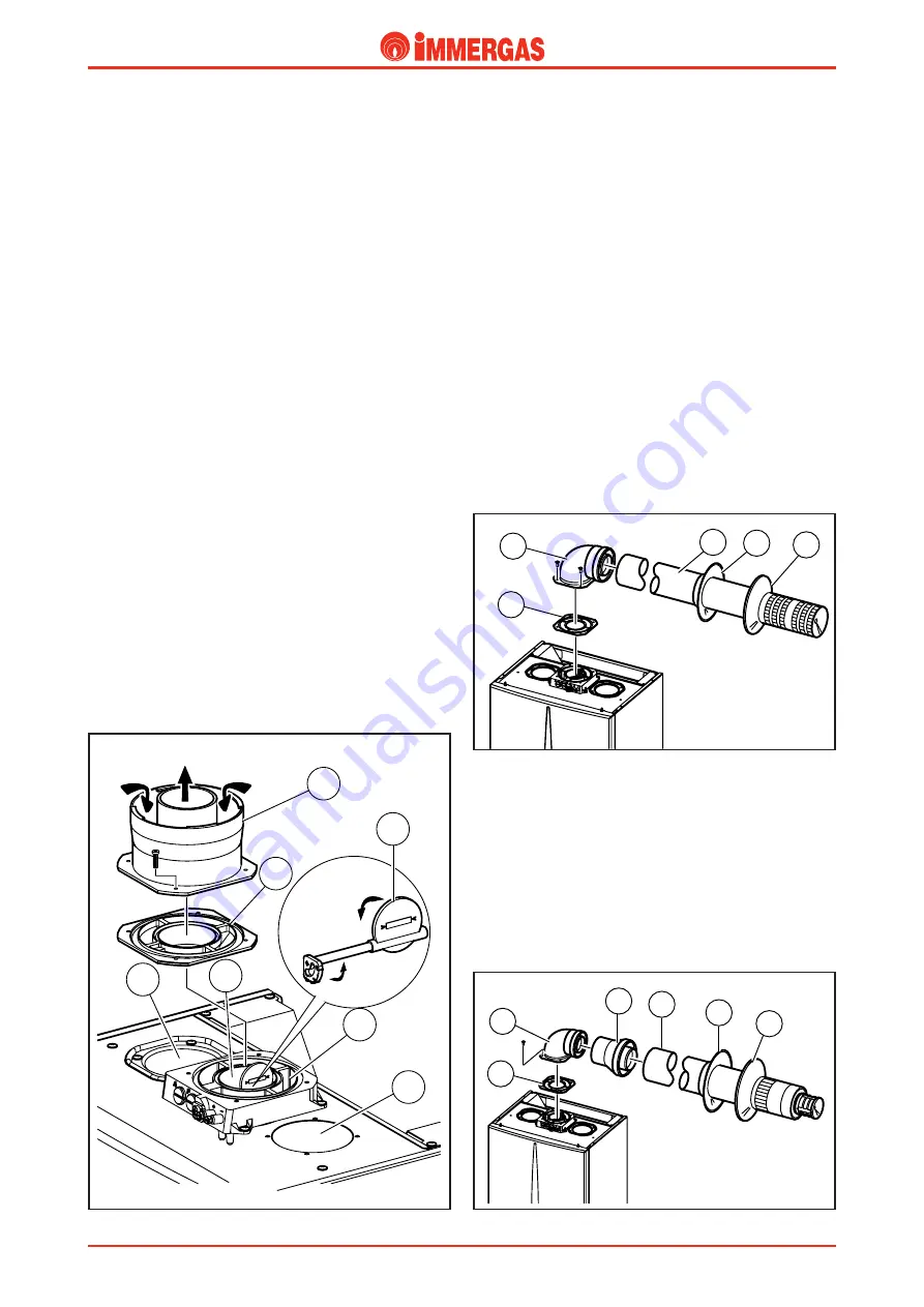
Coupling type horizontal concentric kit 60 /100.
The exhaust pipe (Ø 60 mm) is fitted inside the extraction
pipe (Ø 100 mm).
Connection to the boiler is made using a 90° curve (2) that
can be positioned in any direction and which, by means of
the necessary extensions, must be connected to the special
extraction and exhaust end (3).
Max possible overall length beyond the first curve (2) is
3
straight and horizontal metres.
1
2
5
4
3
Coupling type horizontal concentric kit 80 /125.
The exhaust pipe (Ø 80 mm) is fitted inside the extraction
pipe (Ø 125 mm).
Connection to the boiler is made using a 90° curve diameter
60/100 (2) that can be positioned in any direction and which,
by means of the adapter 60/100-80/125 (3) and necessary
extensions, must be connected to the special extraction and
exhaust end (4).
Max possible overall length beyond the first curve (2) is
7.3
straight and horizontal metres.
1
2
6
4
3
5
1
2
3
5
4
6
7
Fan-assisted, sealed chamber configuration
(type C).
Exhaust.
Connection to the exhaust pipes is by means of a flange (1) or
a flanged bend to connect to fitting (4) on top of the sealed
chamber, placing a special shaped seal in between (6).
The flange differs according to whether the split or concentric
system is used.
In the first case, the passage for the air inlet of combustion air
(5) is closed while, in the second case, it is used.
The flue shutter (7) is mounted on the exhaust fitting (4) which
has to be adjusted to ensure correct boiler operation.
The appropriate adjustment depends on the type of pipe used
and its length
(see boiler instruction handbook).
To adjust, unscrew the front stop screw and move the gradu-
ated indicator to the correct position, aligning the value to the
horizontal reference.
Air inlet.
Using the split system, connection to the air inlet pipes is
exactly the same as for the exhaust pipes, connecting to the 80
mm diameter hole (2) at the top of the sealed chamber.
The unused hole is closed with one of the caps (3) supplied
with the boiler.
If coaxial pipes are used, air inlet occurs by using the concentric
hole outside the exhaust pipe (5).
Summary of Contents for EOLO Maior kW
Page 2: ......


