background image

INSTRUCTIONS FOR USE 

BS300 PLUS SHIing ED.2010 rev.00 


33 

12 - INDIVIDUAZIONE DIFETTI  
La soluzione alla maggior parte degli inconvenienti che potranno verificarsi durante il lavoro puo' essere 
individuata consultando questo capitolo. 
La prima parte riguarda il funzionamento della macchina e comprende un elenco di possibili difetti con i 
relativi controlli da eseguire; 
La seconda parte e' dedicata agli inconvenienti che possono essere rilevati dall'esame della lama e/o dei 
pezzi tagliati. 
Se il problema non e' compreso tra quelli previsti od e' necessario l' intervento di personale specializzato 
contattate il Costruttore o il Rivenditore tenendo a disposizione questo manuale. 
 
 12.1 - DIFETTI DI FUNZIONAMENTO DELLA MACCHINA 

Inconveniente                                            


 Verificare    

A* motore elettrico non gira (per lama)               

  3-4-5-9     

B* motore elettrico non gira (per centralina idraulica)  

  1-2-3-4-5-9-17 

C* controllo elettronico non si accende                 


  6-7-8-9-              

D* circuito idraulico non in pressione              


 10-11-12-13- 

E* pompa idraulica rumorosa                           


 14-15-16-17 

F* liquido refrigerazione manca o e' insufficiente   

 18-19-20-21 

G* pezzo da tagliare si muove o si deforma              

  22-23 


Elenco parti da verificare 

1 = Spina ben inserita nella presa 
2 = Interrutore generale non inserito 
3 = Motore bruciato o danneggiato 
4 = Alimentazione elettrica non corretta 
5 = Trasmissione bloccata (grippaggio, ossidazione, etc) 
6 = Fusibile sul primario del trasformatore 
7 = Fusibile sul secondario del trasformatore 
8 = Trasformatore in avaria o bruciato 
9 = Morsetti di collegamento dei fili di alimentazione 
10= Livello olio nel serbatoio  
11= Perdite da tubazioni e/o raccordi 
12= Vite di regolazione della valvola di massima pressione allentata 
13= Valvola di massima pressione rotta 
14= Qualita' dell'olio idraulico (esausto, troppo liquido) 
15= Acqua nell'olio e/o condensa nel serbatoio 
16= Pressione del circuito troppo elevata (sopra i 20 BAR) 
17= Pompa idraulica bloccata (grippaggio, dilatazione, ossidazione) 
18= Rubinetti del circuito chiusi 
19= Filtri refrigerante occlusi o da pulire 
20= Elettropompa non funzionante ( vedere 3-4-5-9-24) 
21= Serbatoio vuoto o con sporco 
22= Avanzamento di taglio eccessivo 
23= Morsa non chiusa sufficentemente, pezzo mal bloccato 
24= Comando LUBRIFICANTE OFF attivo (-pos.22/RI0055 per modelli SH-E, SHI-E) 
 
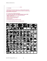
12.2 - DIFETTI DEL NASTRO/CAUSE/RIMEDI  
In caso di denti rotti, nastri rotti o durata nastro nonsufficiente, stendere il nastro, rotto, per terra e controllare 
i difetti del corpo e dei denti, cercarli sulla tabella qui di seguito riportata e leggere la soluzione al problema di 
taglio. 
 
1)PREMATURA ED ECCESSIVA USURA DEI DENTI= 
pressione spinta troppo leggera; aumentarla; 
ridurre la velocita' dei volani; 
getto refrigerante scarso; 
emulsione non apropriata ; 
dentatura non giusta: usare un nastro con una piu' fitta; 
non idoneo rodaggio nastro; 

Summary of Contents for BASIC 300 PLUS SHI

Page 1: ...USE BS300 Plus SHIing ED 2010 rev 00 1 66 IMET Spa Loc Tre Fontane Cisano Bergamasco Tel 035 4387911 Fax 035 787066 Web site www imetsaws com E mail imet imetsaws com Manual Bandsaw BASIC 300 PLUS SHI Semiautomatic Hydraulic INSTRUCTIONS FOR USE ...

Page 2: ...user is responsible for the installation and use of this machine in compliance with the manufacturer s instructions shown in this manual This equipment meets the protection requirements in accordance with the Directives 2006 42 EEC 2004 108 CE for Electromagnetic Compatibility EMC In particular it follows the technical guidelines of the Directives EN55011 EN50082 2 and it has been made for industr...

Page 3: ... Serial number IT IS IN COMPLIANCE WITH THE DIRECTIVES DIRECTIVE 2006 42 CE OF THE EUROPEAN PARLIAMENT AND OF THE COUNCIL OF THE 17TH 05 2006 REGARDING THE MACHINES AND THAT MODIFIES THE DIRECTIVE 95 16 CE DIRECTIVE 2004 108 CE OF THE EUROPEAN PARLIAMENT AND OF THE COUNCIL OF THE 15 12 04 REGARDING THE ELECTROMAGNETIC COMPATIBILITY EMC DIRECTIVE 2006 95 CE OF THE EUROPEAN PARLIAMENT AND OF THE COU...

Page 4: ...INSTRUCTIONS FOR USE BS300 Plus SHIing ED 2010 rev 00 4 66 ...

Page 5: ... the good results of the work Useful is the European Guideline 2003 10 CE The noise depends mostly on the cutting material on its size and on the clamping Considering that the above mentioned decibels could be exceeded we recommend the operator to use personal protections headsets plugs and so on when working for a long time with high noise levels 3 1 ADDITIONAL HEALTH AND SAFETY REQUIREMENTS The ...

Page 6: ...ons made on the equipment or by the use of the machine in a place not corresponding to the indicated environmental specifications 4 1 The manufacturer does not offer further warranties written or spoken explicit or implicit of its products and does not offer implicit warranties on suitability for particular uses not foreseen by the agreement or on chances of selling them The a m limitations and ex...

Page 7: ...shipping 8 9 Fittings Accessories 10 10 Blade choice 12 11 Instructions for use and warnings 14 12 Machine description 17 13 Machine Set up 17 14 Blade tension 18 15 Drivers Description 19 16 Adjustments 22 17 Maintenance for the user 24 18 Blade run in 25 19 Machine run in 25 20 Draining of used produced substances 26 21 Trouble shooting 26 22 Machine demolition 29 24 Maintenance for qualified te...

Page 8: ...t for loading table equipped with roller 300mm wide Adjustable bar stop blade cleaning brush bi metal blade Possibility to connect a foot pedal to start the cutting cycle Main switch with minimum tension coil emergency button thermic and magnetic motor protection motor absorption device Floor stand with removable chip collector tank Tank with coolant electro pump hydraulic unit with oil Tools and ...

Page 9: ...ectronic variable speed drive unit ESC in order to connect the differential protection on the power supply line switches with a threshold of interference on the power dissipation of not less than 300 mA size 0 3 A or higher is recommended have to be employed having possibly time adjustment availability 0 1 5 sec E M C Electromagnetic noise The user is responsible for installing and using this saw ...

Page 10: ...y while slinging and moving the machine in order to hinder damages All operations have to be conducted with graduality so as to avoid jolts and dangerous situations The person in charge of the operations has to make sure that all the national local and company norms in reference to injury prevention and work safety are respected Onr or more areas for material storage have to be identified Transpor...

Page 11: ...all them correctly the saw must be fixed to the floor The machine is equipped with connection for loading table left side Remove the roller to connect the first element of the loading table type RTS To connect the unloading table right side type RTS RTM or RTD the connection element RAB2PS is required Start aligning the roller tables with the one which is nearest to the saw In case of long bars it...

Page 12: ... pressure The switch of the electric system working with low tension 24V AC allows to turn it off at any moment and use the normal coolant system Voltage transformer to be placed between the electric equipment of the building and the electric supply of the machine It allows to work with a different voltage than the standard one 400V 50 Hz Available voltages 230V 460V 500V 575V ...

Page 13: ...ch big teeth to cut solids or particular sections that require at times a big blade effort for example the central part of a U profile or softer materials as aluminium copper soft bronze By choosing the right one you can avoid a lot of working errors get a good cut and the necessary room for the chips If you cut more bars at the same time you must consider them as a single bar and consider the tot...

Page 14: ...0 40 1 LOW 10 St50 St60 10050 10060 50 35 1 LOW 10 HARDENING STEEL C10 C15 10301 10401 45 35 1 LOW 15 16MnCr5 20CrMo5 17131 17264 40 30 1 Low Med 10 AUTOMATIC STEEL 9S20 10SPb28 10711 70 50 1 2 LOW 15 BEARING STEEL 100Cr6 13505 50 25 1 Med Hig 5 SPRING STEEL 65Si7 15028 40 30 1 Med Hig 5 2 TOOL STEEL UNALLOYED C80W1 C125W 11525 11663 40 30 1 HIGH 5 ALLOYED 210Cr12 X155CrVMo 12080 12379 30 20 1 HIG...

Page 15: ...rganized work area with suitable light and operating room 8 the whole equipment has to be correctly and constantly maintained and inspected on a regular basis 9 never use tools with different features from those for which the machine is designed for 10 never use this machine to cut material bigger than the cutting capacity 11 keep the cutting area clear of tools or other loose objects 12 never ope...

Page 16: ...HIing ED 2010 rev 00 16 66 On some parts of the machine there are some stickers which warn about the safety measures that have to be taken by the operator who runs it Their meaning easy to understand is indicated in the following chart ...

Page 17: ...ength diminishes the machine stops immediately Sensor of the closing of the blade protection if it opens while working the machine stops 11 2 2 PROTECTION AGAINS ACCIDENTAL CONTACTS Complete metallic main protection of the blade the pulleys and the back blade driving pad Forward metallic movable guard fixed to the forward blade driving pad It assures the coverage of the blade in every position exc...

Page 18: ... best way and for a very long time 63LW 13 MACHINE SETTING FOR STARTING Verify that the machine has not apparent damages or faults and check the standard equipment that includes tools fittings to carry out some adjustments use and maintenance handbook In case the machine is supplied with additional equipment make sure that it is suited to the machine Inform promptly the Imet dealer about damages o...

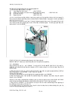
Page 19: ...he EMERGENCY button has been pushed restore it by turning it 1 4 of a round in the direction shown 5 RI0292 b by pushing the button ON of the main switch 10 RI0292 the WHITE light has to turn on c push the button RESET 10 RI0292 to start the hydraulic unit motor the green light which indicates that the blade guard is closed may turn on and check that the sawframe moves up and down by means of the ...

Page 20: ...tection for the whole system including minimum tension release device 2 Analogical device to check the motor power absorption 3 Control panel including check lights 5 Emergency button it stops all drivers when activated to restore the system turn the button 1 4 of a round in the direction shown by an arrow 6 Vice opening closing 7 Sawframe up down 8 Start button for semiautomatic cycle 9 Start but...

Page 21: ...ustable 15 1 WORKING After switching the saw on pos 1 RI0292 if all lights are off the RESET button has to be pushed 9 RI0292 to activate all drivers and the hydraulic unit if no action is taken in a 10 minute span they turn off automatically a Place the material in the vice clamp it manually and then open the vice again by approximately a half turn and put the selector pos 6 RI0292 on the close v...

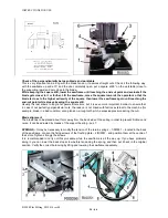
Page 22: ...n case it has been pushed d Turn on the oil pump and close the vice Check if the bar is effectively clamped and if the closing pressure does not deform it e Place the mobile forward blade guide by loosening the handle 19 RI0303 in a position close to the material but not colliding with it or the jaws when the sawframe drops Make sure to lock this handle before using the saw 15 3 SEMIAUTOMATIC CYCL...

Page 23: ...S with the machine switched off except for point 16 3 16 4 16 1 Vice picture RI0056 Guides Play Adjustment by means of nuts and screw with the vice selector in the open position when the vice is completely open loosen all nuts pos 2 and starting with the first screws pos 3 tighten them more strongly continue with the screws that are aligned with the fixed part of the vice pos 4 and lock them with ...

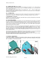
Page 24: ...but it is even more important in order to ensure that in case of not perfectly perpendicular cuts the reason is not linked with factors external to the machine for example blade in a bad condition wrong tension wrong tooth pitch excessive pressure during the cut Blade alignment The blade has to be placed about 1mm away from the back side of the pulley in order to prevent frictions and noise It can...

Page 25: ...blade guard and fix it with the upper hook remove the forward and backward protection loosen the blade tension device by means of the front screw Remove first the blade from the pulleys then from the blade guides using protective gloves while carrying out these operations Make sure that there are no chips or dirt on the pulleys and following the cutting direction shown also by an arrow put the new...

Page 26: ... BIG CHIPS MAYBE BLUE BROWN indicate overload on the blade poor lubricating SPIRAL AND RIGHT DEVELOPED CHIPS indicate the ideal cutting conditions For a correct use see the paragraph BAND CHOICE 19 MACHINE RUN IN The maintenance required by this machine is essential to guarantee the continuous correct working over the course of time and keep the saw in an efficient condition When you start to use ...

Page 27: ...terials that can t be used anymore for example ferrous and non ferrous chips tools such as blades and so on substances used for cleaning and maintenance materials used for specific needs for example when packing shipping and so on Do not throw the packing away as it could be used in case you should return the machine to the dealer or to the service staff when the saw is still under warranty ...

Page 28: ...nastro Solo dopo aver tagliato 250 350 cmq di materiale è possibile aumentare la velocità di penetrazione fino al valore normale L insieme delle condizioni d uso applicate può essere valutato anche esaminando i trucioli prodotti dal taglio si riconoscono solitamente tre varianti TRUCIOLI FINI O POLVERIZZATI indicano scarsa pressione d avanzamento e o velocità bassa dentatura troppo piccola TRUCIOL...

Page 29: ...17 F Not enough coolant 18 19 20 21 G The work piece moves or gets deformed 22 23 LIST OF THE PARTS THAT MUST BE CHECKED 1 Plug correctly inserted in the socket 2 Main switch 3 The motor is burned or damaged 4 Electric supply is not appropriate 5 Transmission hindered 6 Fuses on the primary of the transformer 7 Fuses on the secondary of the transformer 8 Transformer damaged or burned 9 Connection ...

Page 30: ... control the chips Too low blade speed The area between the teeth are full of chips 4 CUTTING SURFACE TOO ROUGH Choose a thinner pitch Increase the blade speed Reduce the sawframe down feed speed Adjust the flow of the coolant 5 EARLY BLADE BREAKING Excessive blade thickness for the diameter of the pulley Blade guides too open with high speed Increase or reduce the speed Check if the pulleys are f...

Page 31: ...EARLY DAMAGE OF THE BLADE STRUCTURE Reduce the blade speed Increase the coolant flow 13 THE BLADE TWISTS LIKE A SPRING Reduce the cutting pressure Reduce the blade tension Excessive blade guides pressure adjust it Move the blade closer to the cutting area 14 THE CHIPS STICK TO THE TEETH CHIPS ARE TOO BIG Reduce the cutting pressure Use proper coolant and in a suited quantity Check the brush used f...

Page 32: ...aining for example the printed circuit display stations programming keyboards buffer batteries and so on especially the ones which shows the picture In these cases in relation with the WEEE AEEE Regulations ask to the supplier to know the right process that depends by the machine size and purpose 23 SPARE PARTS The choice of the required spare parts is aided by the included drawings that allow tog...

Page 33: ...a 5 Trasmissione bloccata grippaggio ossidazione etc 6 Fusibile sul primario del trasformatore 7 Fusibile sul secondario del trasformatore 8 Trasformatore in avaria o bruciato 9 Morsetti di collegamento dei fili di alimentazione 10 Livello olio nel serbatoio 11 Perdite da tubazioni e o raccordi 12 Vite di regolazione della valvola di massima pressione allentata 13 Valvola di massima pressione rott...

Page 34: ...meglio il refrigerante 5 PREMATURA ROTTURA DEL NASTRO spessore lama troppo alto per il diametro dei volani guidalama troppo aperti ad alta velocita aumentare o diminuire la velocita controllare che i volani siano senza difetti dentatura troppo grossa tensione nastro troppo elevata il nastro sdraiato si alza ai lati spinta dell arco troppo forte il dorso del nastro e lucido e ricalcato i cuscinetti...

Page 35: ...alama eccessiva regolarla avvicinare i guidalama al taglio 14 IL TRUCIOLO SI SALDA AL DENTE TRUCIOLI TROPPO GROSSI diminuire la pressione di taglio usare refrigerante idoneo e abbondante controllare l usura della spazzola per la pulizia dei trucioli dalle gole 15 IL NASTRO E SEGNATO O RIGATO DA UN LATO controllare l usura degli inserti dei guidalama gli inserti premono troppo sul dorso del nastro ...

Page 36: ...UCTIONS FOR USE BS300 PLUS SHIing ED 2010 rev 00 36 63PC 23 2 OIL AND LUBRICANTS In the following chart you can find information on the oils and lubricants of different brands that can be used with this saw ...

Page 37: ...ili sbagliati provoca alterazioni sensibili anche di questi valori pregiudicando la salute del personale oltre alla buona riuscita del lavoro Il rumore emesso e in gran parte dipendente dal materiale da tagliare le sue dimensioni e dal sistema di bloccaggio Prevedendo che tali valori vengano superati e consigliabile per l operatore impiegare mezzi personali di protezione cuffia tappi auricolari in...

Page 38: ...ingranaggi olio per impianti di lubrorefrigerazione etc materiali di scarto della lavorazione o non piu utilizzabili es trucioli ferrosi o non utensili tipo lame a nastro dischi etc sostanze utilizzate per pulizia e manutenzione materiali usati solo in alcune fasi di vita della macchina es per l imballaggio il trasporto etc E necessario conservare l eventuale imballo che puo essere riutilizzato pe...

Page 39: ... completa soddisfazione dell utilizzatore La garanzia di cui sopra non e applicabile nel caso di danni accidentali danni provocati da uso scorretto del prodotto da un tipo di manutenzione non corretta da modifiche apportate o dall utilizzo in ambienti non conformi alle specifiche ambientali indicate 16 2 La ditta costruttrice non offre ulteriori garanzie scritte o verbali esplicite od implicite ri...

Page 40: ...0 40 16 4 I componenti sostituiti nel corso di una assistenza prestata dalla ditta costruttrice sono coperti da una garanzia di 6 mesi dalla data di installazione riportata sul modulo di Intervento Tecnico rilasciato in copia al richiedente tale servizio ...

Page 41: ...ere piu approfonditamente la macchina 17 1 Norme per la richiesta dei particolari E necessario comunicare al Servizio Assistenza i seguenti dati numero di matricola indicato sulla targa di identificazione modello versione tipo voltaggio e frequenza di alimentazione numero di codice del i particolare i quantita richiesta eventualmente accessori installati in seguito 17 2 TABELLA COMPARATIVA OLI E L...

Page 42: ...led knowledge of this machine you can find here enclosed Electrical scheme s divided into theme tables and made according to the current norms concerning this subject with index material indication reference code numbers Pneumatic and hydraulic circuits Drawings divided into the main parts the saw is comprised of They code description and quantity of each component The electrical electronic pneuma...

Page 43: ...INSTRUCTIONS FOR USE BS300 PLUS SHIing ED 2010 rev 00 43 ...

Page 44: ...INSTRUCTIONS FOR USE BS300 PLUS SHIing ED 2010 rev 00 44 ...

Page 45: ...INSTRUCTIONS FOR USE BS300 PLUS SHIing ED 2010 rev 00 45 ...

Page 46: ...INSTRUCTIONS FOR USE BS300 PLUS SHIing ED 2010 rev 00 46 ...

Page 47: ...INSTRUCTIONS FOR USE BS300 PLUS SHIing ED 2010 rev 00 47 ...

Page 48: ...INSTRUCTIONS FOR USE BS300 PLUS SHIing ED 2010 rev 00 48 ...

Page 49: ...INSTRUCTIONS FOR USE BS300 PLUS SHIing ED 2010 rev 00 49 ...

Page 50: ...INSTRUCTIONS FOR USE BS300 PLUS SHIing ED 2010 rev 00 50 ...

Page 51: ...INSTRUCTIONS FOR USE BS300 PLUS SHIing ED 2010 rev 00 51 ...

Page 52: ...INSTRUCTIONS FOR USE BS300 PLUS SHIing ED 2010 rev 00 52 ...

Page 53: ...INSTRUCTIONS FOR USE BS300 PLUS SHIing ED 2010 rev 00 53 ...

Page 54: ...INSTRUCTIONS FOR USE BS300 PLUS SHIing ED 2010 rev 00 54 ...

Page 55: ...INSTRUCTIONS FOR USE BS300 PLUS SHIing ED 2010 rev 00 55 ...

Page 56: ...INSTRUCTIONS FOR USE BS300 PLUS SHIing ED 2010 rev 00 56 ...

Page 57: ...INSTRUCTIONS FOR USE BS300 PLUS SHIing ED 2010 rev 00 57 ...

Page 58: ...INSTRUCTIONS FOR USE BS300 PLUS SHIing ED 2010 rev 00 58 ...

Page 59: ...INSTRUCTIONS FOR USE BS300 PLUS SHIing ED 2010 rev 00 59 ...

Page 60: ... ARCO 280 SHE SHI E VELOX SHE AF FEED CONTROL LEVER BS280 VELOX 136827 ASTA REG MISURA BS350 280 BRUN D 20 FILETTO M12 LENGTH STOP ROD D 20 BS340 280 142719 BASAMENTO GHISA BS280 PLUS CON CAVA SCOR CAST IRON BASE GROOVE BS280PLU 144999 BIELLA OTTON TPN25 MORSA BS280 PLUS VICE THREADED ROD BS280 SCHRAUBST GEWINDEPLEUE LSTANGE 157210 BLOCCHETTO TENDINASTRO 280350 FRONTALE BAND TENSIONER BLOCK 280350...

Page 61: ...L CONTROL COVER SHI SHIE 276674 CORONA BRONZ M2 75 Z35 BS280 BRONZE WHEEL M2 75 Z35 BS280 279150 CUNEO SX BLOC MORSA SIRIO370 SIRIO370 VICE ADJ LEFT WEDGE COIN GAUCHE BLOCAGE ÉTAU S 370 279160 CUNEO DX BLOC MORSA SIRIO370 SIRIO370 VICE ADJ RIGHT WEDGE COIN DROI BLACAGE ÉTAU S 370 280052 CUNEO REGISTR MORSA BS280 PLUS L 452 CON 2 FORI SPINA VICE ADJUSTING WEDGE BS280PLUS 283011 CUSCINETTO 32005X 25...

Page 62: ...DBM196133 M BS350 280 D50XD34X20 5 SAW FR CYL GASKET MDB2X400501 511300 GUARNIZIONE LANTERNA BS280 120 X80 GASKET BS 280 511330 GUARNIZIONE FLANGIA BS280 D 14 5X110 FLANGE GASKET BS 280 D 14 512497 GUIDA HIWIN HGR15R340C BS300 FORO 20MM TASTATORE280 300 GUIDE HIWIN LGR15R340C 20 20 513095 IMPUGNATURA NERA 20X80 PLAST X ASTA PLASTIC BLACK HANDLE D 20X80 513931 IMPUGNATURA SFERA NERA D 12X40 MONT PR...

Page 63: ...O 547316 MOLLA NASELLO BASAM BS280 350 BASE SPRING BS280PLUS 340 350 GRUNDLAGE NASE FEDER BS280 350 547652 MOLLA PER ARCO BS230 280 350 3 40 SAW FRAME RETURN SPRING 340280 RESSORT RAPPEL ARCHET BS340 BS RAHMEN RUECKFEDER BS340 BS280 590050 MOT 3F 2 4P FC90TP B5 V400 280 CE 1 7 1 3 B5 SENZA CHIAVETT 3PH MOTOR 2 4P FC90 V400 B5 614397 6 10 NASTRO 280 2765X27X09 M42SVGLB STB DENTATURA 6 10 HV950 BAND...

Page 64: ...AGER FUER BANDFUEHRUNG 697836 PORTA ELETTROPOMPA X VASCHETTA DELTA ELECTROPUMP SUPPORT ELEKTROPUMPETRAGER 698045 PORTARULLO W30 CAR BS280 PLUS NEW UNLOAD W30 ROLLER HOLDER BS280 SUPPORT ROULEAU BS280PLUS GH ABFUHR ROLLERTRAGER BS280 699580 PORTA FINCORS MOLLE NASTRO 280 350 FRONTALE BAND FRONT STROKE END HOLDER BAND VORD ENDSCHALTER TRAGER 699591 PORTA FINCORS ARCO FINE TAGLIO MACCHINE CON TASTATO...

Page 65: ...GEL D 12 GRUNDPLATTE BS280 780850 SNODO UNIBALL SMG10 M10 MASCHI O UNIBALL JOINT SMG10 M10 UNIBALL GELENK SMG10 M10 ZAPFE 785682 SPAZZOLA FERRO D 50 PERNO6x25 G1052 BLADE CLEANING BRUSH 6X25 BROSSE DIA 50 6X25 G1052 786162 SPIA OLIO HE45 PERFECT RECORD 280 COD 12001 OIL SIGHT GLASS HE45 PERF REC PERFECT RECORD BOUCH NIVEAU OELSCHAUGLAS HE45 PERF REC 788270 SPINA EL SPIROL 5X10 DIN7343 ELASTIC PIN ...

Page 66: ...ASCHETTA ELETTROPOMPA DELTA20 447X314X200 20 LITRI GRIGIO ELECTRIC PUMP TANK DELTA 20 ELEKTROPUMPE BEHAELTER DELTA20 956843 VITE TE M14X30 SIN SVASATA LEFT SCREW TE M14X30 VIS GAUCHE TE M14X30 957148 VITE MORSA BS300 PLUS IDRAULIC A VICE SCREW FOR BS 300 SHI SCHRAUBSTOCK SCHRAUBE BS300SHI 958928 VITE SENZA FINE BS280 ENDLESS SCREW BS280 SCHNECKE BS 280 962390 VOLANTINO ART 751 32 M8X30 BS280 WHEEL...

Reviews: