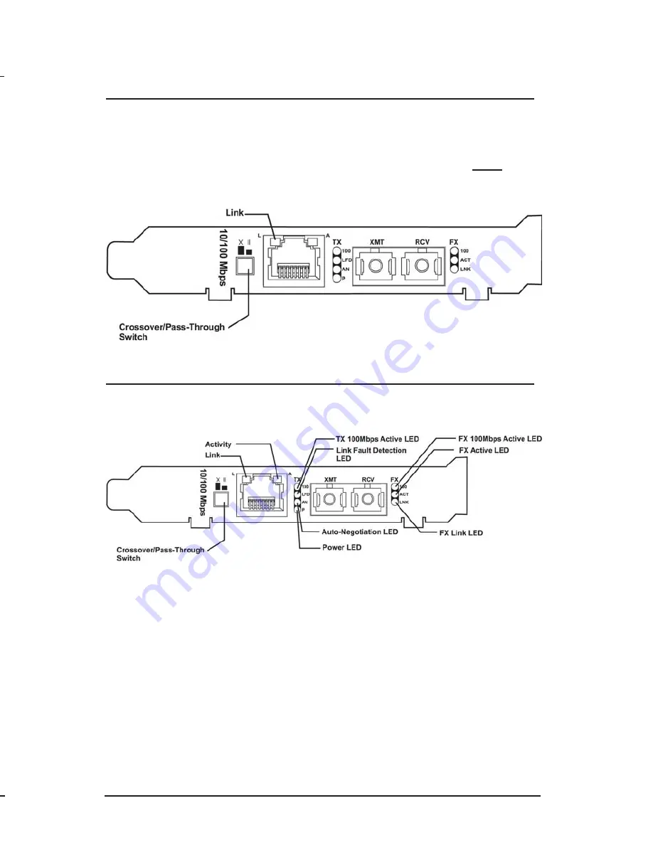
Tw i s t e d P a i r C r o s s o v e r / P a s s -
T h r o u g h B u t t o n
The McPC 10/100 features a crossover/pass-through button, located on
the faceplate next to the RJ-45 connector, to set the twisted pair
connection type. Select a pass-through connection by pressing the
button. A crossover connection is selected when the button is
OUT
. If it
is not known which connection is needed, set the button to whatever
setting makes the twisted pair LNK (link) LED glow.
LED Indicators
The McPC 10/100 features several diagnostic LEDs per port. The LED
functions are as follows:
T
W I S T E D
P
A I R
P
O R T
L
Glows green when a twisted pair link is established.
A
Glows yellow when activity is detected on the port.
100
Glows yellow when a 100 Mbps connection is detected.
LFD
Glows green when Link Fault Detection is enabled.
(
NOTE
: This feature is only available when either
Force 10
or
Force 100
mode is enabled. For more on this feature, see the
LFD LED Activity section below.)
AN
Glows green when Auto-Negotiation mode is enabled.
P
Glows green when unit has power.
Modes of Operation
The McPC 10/100 features three modes of operation:
Auto-
Negotiation mode
,
Force-10 mode
and
Force-100 mode
. Configure the
McPC 10/100 for one of these modes (factory default is AN mode). Refer
to the Link Fault Detection section for information on Link Fault
Detection.
•
Auto-Negotiation mode
is the mode most ideally suited for the
McPC 10/100. In this mode, the converter will optimally and
automatically configure for speed (10 or 100 Mbps) depending on
the capabilities of the end stations.
To enable Auto-Negotiation mode, set switch
6
to the
ON
position,
with switches
7
and
8
in the
OFF
position.
• In
Force 10 mode
, the McPC 10/100 acts as a 10Base-T to 10Base-
FL media converter; 100 Mbps signals are not accepted.
To enable
Force 10 mode
, set switch
7
and
8
to the
ON
position,
with switch
6
in the
OFF
position.
8
3
N
OTE
The PC Media Converter cannot be manually set for Half- or Full-Duplex.
Duplex is determined by the devices to which PC Media Converter is connected.


