background image

OBS

+

OP

+

5050D and OPSS

+

OP

+

D Installation and Operation Manual

xi

Preface


Safety Terms and Symbols

This product manual uses the following safety terms and symbols to 
identify certain conditions or practices. See 

“Laser Safety” on page 30


and the

 6800

+

 Series Safety Instructions and Standards

 booklet for 

more information. 

WARNING

CAUTION

Table P-3. 

Safety Terms and Symbols

Identifies conditions or practices that can result in personal 
injury or loss of life—high voltage is present. Uninsulated 
dangerous voltage within the product’s enclosure may be 
sufficient to constitute a risk of electric shock to persons.

Identifies conditions or practices that can result in damage 
to the equipment or other property. Important operating and 
maintenance (servicing) instructions are included in the 
literature accompanying the product.

Summary of Contents for OBS+OP+5050D

Page 1: ...Delivering the Moment Installation and Operation Manual OBS OP 5050D OPSS OP D 50 50 Splitter Protection Switch Edition B 175 000332 00...

Page 2: ...foCaster Player Nexio InfoCaster Traffic Nexio InstantOnline Nexio mCAPTURE Nexio News Force Nexio NXIQ Nexio Playlist Nexio Remote Nexio RTX Net Nexio TitleMotion Nexio TitleOne Nexio Velocity ESX Ne...

Page 3: ...OBS OP 5050D 50 50 Splitter OPSS OP D Protection Switch Installation and Operation Manual Edition B March 2007...

Page 4: ......

Page 5: ...escriptions 3 Front Modules 3 Back Modules 4 Typical Fiber Transmission Configurations 5 Signal Flow 6 Typical Broadcast and Production Applications 6 Chapter 2 Installation Maximum FR6802 Frame Power...

Page 6: ...Procedure 18 Chapter 3 Operation Operation Notes 22 Setting Parameters 22 LEDs and Alarms 23 LEDs 23 Alarms 24 Chapter 4 Specifications Optical Specifications 26 Power Consumption 27 Start Up Time 27...

Page 7: ...050D 50 50 splitter and OPSS OP D protection switch Audience This manual is written for engineers technicians and operators responsible for the installation setup and operation of the OBS OP 5050D 50...

Page 8: ...ets fields buttons check boxes list boxes combo boxes menus submenus windows lists and selection names Italics Indicates email addresses the names of books or publications and the first instances of n...

Page 9: ...return a product for servicing In the unlikely event that your product fails to operate properly please contact Customer Service to obtain a Return Authorization RA number then send the unit back for...

Page 10: ...Simplified Receptacle SC PC Connector Interfaces IEC 60874 14 2 Detail Specification for Fiber Optic Connector Type SC PC Tuned Terminated to Single Mode Fiber Type B1 IEC 60874 14 5 Detail Specificat...

Page 11: ...t The intent of this legislation is to reduce the amount of hazardous chemicals that may leach out of landfill sites or otherwise contaminate the environment during end of life recycling The Directive...

Page 12: ...cycle electrical and electronic equipment at end of its useful life and may not dispose of the equipment in landfills or by using other unapproved methods Some EU member states may have different dead...

Page 13: ...rmation WARNING CAUTION Table P 3 Safety Terms and Symbols Identifies conditions or practices that can result in personal injury or loss of life high voltage is present Uninsulated dangerous voltage w...

Page 14: ...xii OBS OP 5050D and OPSS OP D Installation and Operation Manual Preface...

Page 15: ...modules The OBS OP 5050D is a 50 50 splitter the OPSS OP D is a protection switch These products are designed to provide fiber link redundancy protection The following topics are described in this ch...

Page 16: ...plits 50 50 the primary and standby fiber signals to provide redundancy protection Main Features These are the main features of the OBS OP 5050D and OPSS OP D products Intelligent auto switching and a...

Page 17: ...3 Chapter 1 Introduction Module Descriptions Front Modules Figure 1 1 shows the OBS OP 5050D and OPSS OP D front modules respectively These modules cannot be used in FR6800 7000 frames Figure 1 1 OBS...

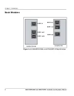
Page 18: ...OPSS OP D Installation and Operation Manual Chapter 1 Introduction Back Modules Figure 1 2 OBS OP 5050D and OPSS OP D Back Modules OBS OP 5050D SC PC in SC PC out 1 SC PC out 2 SC PC in 1 SC PC in 2 S...

Page 19: ...duction Typical Fiber Transmission Configurations Figure 1 3 and Figure 1 4 illustrate typical fiber transmission configurations for unidirectional and bidirectional systems respectively Figure 1 3 Un...

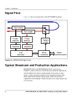
Page 20: ...dcast cable production educational and auditorium applications Typical applications include sending signals from studios remote trucks or other production facilities to the transmission site facility...

Page 21: ...the Modules on page 11 See the FR6802 Frame Installation and Operation Manual for information about installing and operating an FR6802 frame and its components OBS OP 5050D and OPSS OP D modules canno...

Page 22: ...panel is closed at all times and that the fan module is fully operational 0 W OBS OP 5050D 2 W OPSS OP D Table 2 1 Frame Power Ratings 6800 Frame Type Power Supply Max Frame Power Dissipation Numbero...

Page 23: ...l other packaging material Retain the original packaging materials for possible re use Contact your Customer Service representative if parts are missing or damaged See Unpacking Shipping Information o...

Page 24: ...2 1 Fiber Input Switch When you select Port 1 Connected or Port 2 Connected using the switch the module accepts the signal as it is received from the designated port When you select Automatic Mode con...

Page 25: ...ions must be inspected and cleaned before they are assembled Carefully follow the inspection and cleaning steps described in the next pages Additional safety information begins on page 30 CAUTION Ensu...

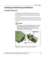
Page 26: ...future configurations 3 On the side of the back module that inserts into the front module remove the inner protective cap from the fiber connection see Figure 2 2 on page 11 CAUTION Microscopic dust...

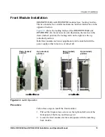
Page 27: ...the down locked position the locking latch on the right is in the up unlocked position Both front modules are hot swappable and can be installed with the power supply either turned on or turned off F...

Page 28: ...t begin on page 16 5 Ensure that your front module matches with a corresponding back module of the same name 6 With the locking latch in the up position slide the module into the guides on the frame f...

Page 29: ...he module The latch should easily slide to its up released position 3 Grasp the extractor handle on the installed module and then pull the module out of its slot use the handle as a lever 4 Close the...

Page 30: ...clean both fiber ends every time you make a connection Keep a protective cap on unplugged fiber connectors Do not touch the end of a fiber Store unused protective caps in a clean resealable container...

Page 31: ...ark Figure 2 4 describes the acceptable limits of defects in a fiber connection Figure 2 4 Fiber Optic Cross Section Zone 2 20 to 50 micron diameter Maximum of 3 scratches 1 0 micron width is acceptab...

Page 32: ...y cleaning instructions below Dry Cleaning If you are using cartridge or pocket style dry cleaning tools follow the manufacturer s directions If you are using lint free wipes follow these steps 1 Fold...

Page 33: ...action on the dry section of the wipe removing any residual alcohol 5 Inspect the fiber endface again and if necessary repeat the wet cleaning with another clean section of the lint free wipe CAUTION...

Page 34: ...20 OBS OP 5050D and OPSS OP D Installation and Operation Manual Chapter 2 Installation...

Page 35: ...ollowing documents for information on how to operate this product remotely Pilot Lite User Manual for serial control interface Installation and Operation Manuals for CCS Navigator Pilot CoPilot NUCLEU...

Page 36: ...d control panels An asterisk indicates the default value or option Parameters with the symbol RO are read only Forced Remote Manual Auto Channel 1 Channel 2 Table 3 1 OPSS OP D CCS Parameters Paramete...

Page 37: ...n Figure 3 1 the OPSS OP D module displays the following card edge LEDs Power Link Down Port 1 OK Port 2 OK Local Mode Port 1 Connected Port 2 Connected Table 3 2 on page 24 describes the meanings of...

Page 38: ...ser intensity levels None The module output is valid according to the Signal Good Threshold parameter setting Port 1 OK Green The Fiber 1 input signal is valid according to the Signal Good Threshold p...

Page 39: ...er 4 Specifications Overview The following specification information appears in this chapter Optical Specifications on page 26 Power Consumption on page 27 Start Up Time on page 27 Temperature on page...

Page 40: ...ch time 15 ms Optical back reflection 35 dB Insertion loss 1 5 dB Maximum input optical power 25 dBm Minimal input optical power 41 dBm Absolute reported power error 3 dB Reported relative power error...

Page 41: ...The OBS OP 5050D requires no power Start Up Time The start up time for the OPSS OP D is approximately 10 seconds the OBS OP 5050D requires no start up time Temperature Table 4 3 Temperature Specifica...

Page 42: ...28 OBS OP 5050D and OPSS OP D Installation and Operation Manual Chapter 4 Specifications...

Page 43: ...llation and Operation Manual 29 Appendix A Laser Safety Guidelines Overview This section describes important safety considerations when using laser modules The following topics are included Laser Safe...

Page 44: ...smission products are classified in four major groups Class 1 2 3 and 4 according to their emissions and potential for causing injury Fiber optic transmitter modules in the OPTO series are designated...

Page 45: ...tion system is considered unenclosed Under these conditions follow these practices Avoid exposing the eye to emissions from unterminated energized optical connectors at close distances Ensure that onl...

Page 46: ...A Laser Safety Guidelines Labels The label shown in Figure A 1 is applicable to Class 1 laser products Figure A 1 Label for Class 1 Laser Products CLASS 1 LASER PRODUCT IEC 60825 1 1993 A1 1997 A2 200...

Page 47: ...Installing a module 7 19 J Jumper information 10 L Laser precautions 11 14 29 32 LEDs 23 24 Locking latches 13 15 M Manual revision history v Manual writing conventions vi Modules back 4 12 15 front 3...

Page 48: ...Manual Index Shipping information vii Signal flow diagram 6 Specifications 26 27 T Transmission configurations 5 U Unidirectional transmission system 5 Unpacking information vii 9 W Warranty informat...

Page 49: ......
Reviews: