


OBS
+
OP
+
5050D and OPSS
+
OP
+
D Installation and Operation Manual
13
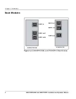
Chapter 2: Installation
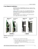
Front Module Installation
OBS
+
OP
+
5050D and OPSS
+
OP
+
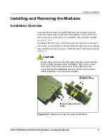
D modules have “locking” latches.
The two modules have similar mechanisms, but their latches face in the
opposite direction.
Figure 2-3
shows the locking latches of the OBS
+
OP
+
5050D and
OPSS
+
OP
+
D. On the left side of each illustration, the latch is in the
down (locked) position; the locking latch on the right is in the up
(unlocked) position.
Both front modules are hot-swappable and can be installed with the
power supply either turned on, or turned off.
Figure 2-3.
Latch Operation
Procedure
Follow these steps to install the front modules:
1. Pull out the finger-release screws on the right and left side of the
front panel of the frame, and then open it.
2. Locate the front module slot that corresponds with the matching
back module.
Down (locked)
position
Up (unlocked)
position
OBS
+
OP
+
5050D
OPSS
+
OP
+
D
Down (locked)
position
Up (unlocked)
position
Summary of Contents for OBS+OP+5050D
Page 4: ......
Page 14: ...xii OBS OP 5050D and OPSS OP D Installation and Operation Manual Preface...
Page 34: ...20 OBS OP 5050D and OPSS OP D Installation and Operation Manual Chapter 2 Installation...
Page 42: ...28 OBS OP 5050D and OPSS OP D Installation and Operation Manual Chapter 4 Specifications...
Page 49: ......