background image

Quick Reference Guide

ÜÜÜ°ˆ“>}i‡Û>Տ̰Vœ“ÊUÊ£‡nnn°{ÈÓ°{ÎnÓÊÉÊ£°n£Ó°™{n°n{ää

VIDEO SECURITY

D I G I T A L

VIDEO SECURITY

D I G I T A L

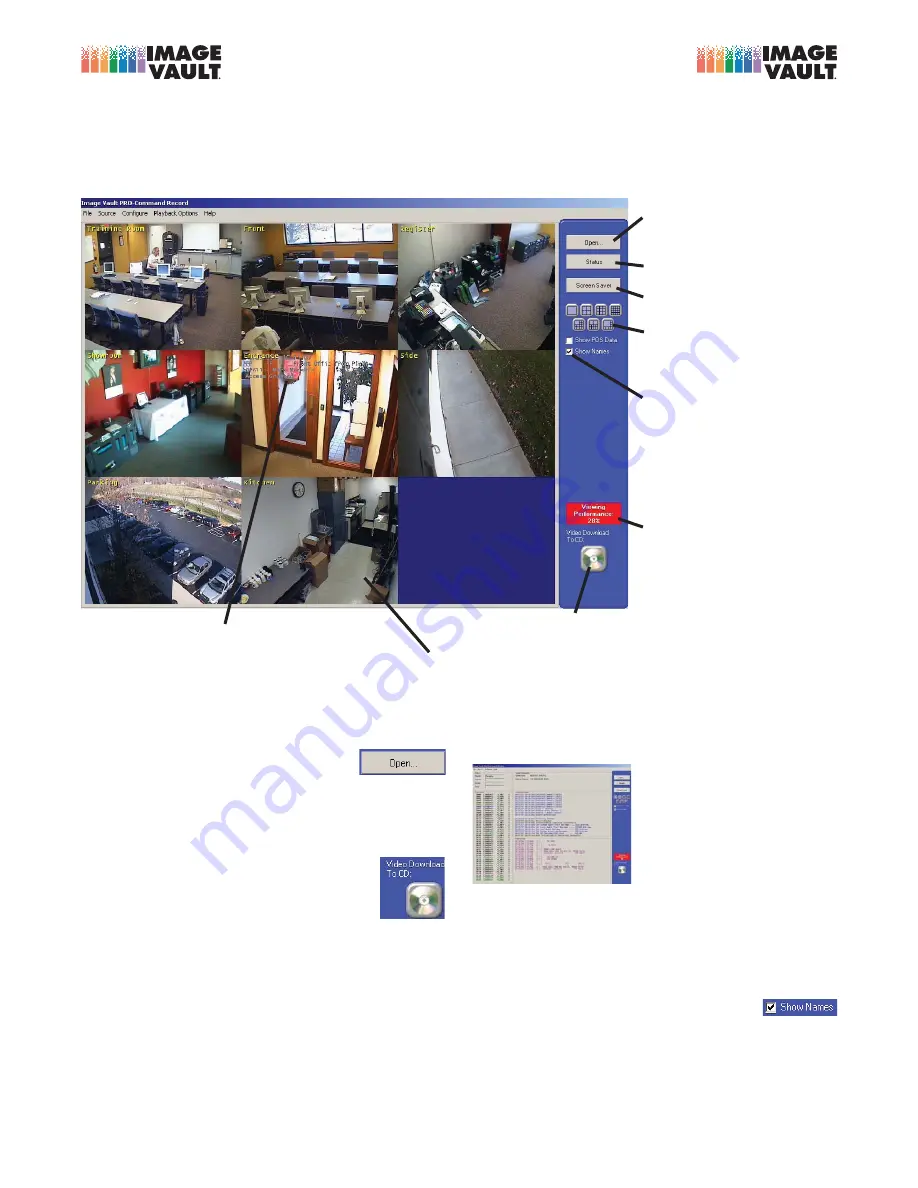
LIVE MONITOR SCREEN

Click on a camera and drag to a new 

location to 

change the camera display order

.

You may show 

live POS data as a text overlay

To enable this feature select the 

Configure menu


then choose

 POS Overlay Setup

Click to 

Play back


stored video.

Switch to 

Live


Status

 Mode.

THIS SCREEN IS USED TO VIEW LIVE VIDEO AS IT IS BEING CAPTURED

Click and drag to change camera order. Change the layout and number of cameras displayed. 

Show or hide camera names, POS data, and motion detection grids. 

Click “Open” to review stored video and data.

Activate the 

Screen Saver

.

When enabled, 

camera 

names

 appear in bright yel-

low in the upper left corner 
of each camera window.

Click any of these icons to 

change the number and layout 
of cameras displayed

.

Click the CD icon to begin making a 

copy of video to CD, DVD, or USB

.

The 

Viewing Performance


indicator lets you know how 
well you are keeping up with 
daily video checks.

FREQUENTLY ASKED...

How do I play back recorded video?

 Click 

Open

 (upper right corner of live monitor 

screen). Enter your user name and password when 
prompted. For additional information flip over to the 
other side of this sheet.

How do I save a clip?

ʘÃiÀÌÊ>ÊL>˜ŽÊÉ6‡

ROM disk or USB mass storage device. 
Click the 

Video Download to CD

 icon (lower 

right corner of live monitor screen) then se-
lect the destination. Playback software will be copied 
along with the most recent video (length of clip de-
pends on destination capacity). To save a clip on the 

6,\ʜ«i˜Ê«>ÞÊL>VŽÊ>˜`ÊV…œœÃiÊ,>˜}iʜVŽÊvÀœ“Ê

the Catalog menu. Choose Copy to Removable from 

>Ì>œ}ʓi˜ÕÊ̜ÊVœ«ÞÊ>ÊëiVˆwVÊVˆ«Ê̜ÊÉ6‡,"Ê

or USB media.

What do I do if I see this screen:


/…ˆÃʈÃÊV>i`Ê̅iʈÛiÊ-Ì>ÌÕÃÊ

screen. It shows image and 
data information as they are 
captured. Click 

Monitor

 to 

ÀiÌÕÀ˜Ê̜Ê̅iʈÛiʜ˜ˆÌœÀÊ

screen.

How do I show (or hide) POS data on the Live Monitor 
screen?

 From the Configure menu select POS Overlay 

Setup (On Site Monitor). Associate data to cameras 
and configure font size and color as desired.

How do I show (or hide) camera names on the Live Monitor 
screen?

 Click 

Show Names

 (option is found 

on the right side of the screen).

x£ÓäÓx

äxÉÓää™

Summary of Contents for Pro-Command

Page 1: ...APPENDIX A Page 1 Installation Manual Pro Command DVR...

Page 2: ...e THE INFORMATION IN THIS PUBLICATION IS PROVIDED AS IS WITHOUT ANY WARRANTY OF ANY KIND THE ENTIRE RISK ARISING OUT OF THE USE OF THIS INFORMATION REMAINS WITH THE RECIPIENT IN NO EVENT WILL IMAGE VA...

Page 3: ...nts 6 Facilities 7 Front Panel 7 Rear Panel 8 Connectivity 11 Mounting DVR 11 Power 11 Input Devices 11 Monitor 11 Network Connections 11 Alarm Connections 12 Capture Cards 13 Connecting a PTZ 15 POS...

Page 4: ...into the battery backup segment of the UPS and be the only attached device Failure to properly install a UPS may cause damage to the systems hard drive resulting in a loss of recorded images or the in...

Page 5: ...d 95 F 35 C Operating Temperature 41 104 F For proper ventilation you must provide 3 inches minimum clearance in both the front and back of the DVR The Image Vault filter item A on diagram 7 1 must be...

Page 6: ...26 IVPTZAOC connection diagram page 24 Warranty Document page 27 Integration Facility Checklist Black Jewel Case with Playback CD and printed manual Window Door Decal x1 Blank CD 10 Patch Cable IVPTZA...

Page 7: ...thly cleaning of the filter is recommended B Power Switch Rocker switch turns the DVR on or off C Reset Switch Push button reset switch causes the DVR to shut down and automatically reboot D On Off In...

Page 8: ...ely remove power Turning this switch on does not automatically start the recorder refer also to Front Panel Power Switch C Mouse For a PS 2 Style Mouse D Keyboard For a PS 2 Style Keyboard E Serial Po...

Page 9: ...les K Capture Card s For connection of up to 32 analog cameras depending on model of DVR utilizing male BNC connectors Also allows for connection of up to two public view monitors PVM utilizing female...

Page 10: ...Image Vault Pro Command version 9 4 3 Installation Manual Page 10 A B G C D E H I J F K L M Rear Panel 32 240 Unit Diagram 9 1...

Page 11: ...8 1 The Image Vault is a mouse driven system and a keyboard is not necessary for setup and use However if you wish to install a keyboard you may connect it to the PS 2 keyboard input D Diagram 8 1 or...

Page 12: ...Image Vault DVR allows up to 16 alarm inputs To connect external inputs you will need a DB25 cable or DB25 pin out connector The pin out is in numerical order Pin 1 is input 1 pin 2 is input 2 This co...

Page 13: ...o connect cameras 9 16 K 1 Diagram 8 1 DB15 to the top female DB port on the capture card The PROC16480 model can connect up to 16 audio inputs Use the provided audio whip cable to connect the audio i...

Page 14: ...15 K diagram 8 1 cameras 9 16 connect DB15 K 1 Diagram 8 1 Image 14 1 The PROC32240 model can connect up to 16 audio inputs Use the provided cable s to connect the audio input on the back of DVR On t...

Page 15: ...ed for proper connection to POS or data devices See Appendix A for more information Serial Connection Direct Connection to a Single Data Device Direct Connection to a Multi Device Server IV Quad Netwo...

Page 16: ...Image Vault Pro Command version 9 4 3 Installation Manual Page 16 Example 1 Single Data Device Example 2 Multi Device Server...

Page 17: ...Example 3 IV Quad Serial Port 2 Serial Port 2 is for an additional direct Point of Sale POS or data device serial connectivity Serial Port 2 doubles the connectivity options serially For example you...

Page 18: ...print server does not require any additional cables The DVR must be connected to the same local network as the POS data source Coordinated software configuration of the network print server s and DVR...

Page 19: ...d to the monitor output s you should begin seeing video from the cameras switching approximately every four seconds by default Wait a minimum of five 5 minutes before attempting to connect to the syst...

Page 20: ...Image Vault Pro Command version 9 4 3 Installation Manual Page 20 Notes...

Page 21: ...lation Manual Page 21 Technical Support 1 888 462 4382 Monday Friday 8AM 5PM EST Image Vault LLC 101 Security Parkway New Albany IN 47150 0559 Phone 888 462 4382 Fax 812 296 0038 www image vault com I...

Page 22: ...IV DB9F IV 25 25 Pin POS Cable Comes with IV DB9F IV G RJ 45 Gilbarco POS Cable Comes with IV DB9F IV DB9F Female 9 Pin DVR cable IV RK Ruby POS Cable IV DB9F IV R Ruby POS Cable IVQ4 POS Quad Interfa...

Page 23: ...APPENDIX B Page 23 Addition Installation Documents In this Section Follow this page...

Page 24: ......

Page 25: ...ices and sounds Neither Image Vault LLC as the manufacturer nor any entity from or through which this equipment and software was purchased can accept any responsibility for such unauthorized use and t...

Page 26: ...Ex Vibrations generated by any machines with direct or indirect contact with the mounting surface of the DVR Installation in a moisture rich area or area with a constant excessive level of relative hu...

Page 27: ...nd implied warranties including the warranties of merchantability and fitness for a particular purpose are excluded except as stated above Image Vault disclaims all liabilities for incidental or conse...

Page 28: ...ts you know how well you are keeping up with daily video checks FREQUENTLY ASKED How do I play back recorded video Click Open upper right corner of live monitor screen Enter your user name and passwor...

Page 29: ...ers On CONTROL PANEL POS TRANSACTION DATA Data may also be superimposed on camera windows PLAYBACK SCREEN The central matte is where camera windows are opened the right side control panel opens and ar...

Page 30: ...APPENDIX A END Pro Command DVR...

Reviews: