background image

I N T R O D U C T I O N   A N D   S P E C I F I C A T I O N S

Specifications

OMH-6722B

C H A P T E R  

1


1. Add + 0.5% from 400 to 450 nm and from 990 to 1100 nm.
2. Minimum optical power required for accurate wavelength measurement:

400 nm ~ 500 nm
100 uW (-10 dBm)

500 nm ~ 1100 nm
10 uW (-20 dBm)

For power measurement below these levels, use MANUAL wavelength mode.

3. For input power > 100 mW:

Add +0.05% / 100 mW to power accuracy
Add +0.05 nm / 100 mW to wavelength accuracy
Example: 500 mW, 850 nm, accuracy = +4.2%, +1.2 nm

4. MANUAL wavelength mode: Add +0.5% for automatic wavelength correction.
5. Wavelength accuracy between 450 nm to 1100 nm.

Our goal is to design and produce the best optical test equipment available 
anywhere. To achieve this, we need your ideas and comments on ways we can 
improve out products. We invite you to contact us at any time with your 
suggestions.

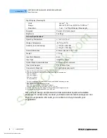
Right Display (Wavelength)

Units

Range

Resolution

nm, cm

-1

Ä

500.0 to 1000.0 nm, 20,000 to 10,000 cm

-1

.1 nm, .1 cm

-1

Right Display (Wavelength)

Bargraph

Percent of full scale power

Brightness

5 settings

General Specifications

Operating Temperature

+ 15 

o

C to +35 

o

C

Storage Temperature 

-40 

o

C to +70 

o

C

Humidity (non-condensing)

> 100 

W: <85% RH

< 100 

W: <70% RH

Overall Dimensions

68.6 mm diameter x 30.1 mm

Weight < 

0.5 

kg

Input Port Diameter

6 mm

Input Type

Integrating sphere

Optical Stand Accommodations

8/32 tapped hole centered

Fiber Optic Adapter

FC, ST, Bare Fiber

Connector to Main Unit

26 pin high-density sub-D

StockCheck.com

Downloaded from StockCheck.com

Summary of Contents for OMH-6722B

Page 1: ... OMH 6722B 70023304_02 March 2014 ILX Lightwave Corporation 31950 Frontage Road Bozeman MT U S A 59715 U S Canada 1 800 459 9459 International Inquiries 406 556 2481 Fax 406 586 9405 ilx custhelp com www ilxlightwave com StockC heck com ...

Page 2: ...StockC heck com Downloaded from StockCheck com ...

Page 3: ...n ix Safety Information and the Manual ix General Safety Considerations ix Safety Symbols x Safety Marking Symbols x Warranty xi Comments Suggestions and Problems xiii Chapter 1 Introduction and Specifications Product Overview 1 Safety Considerations 1 Available Options and Accessories 2 Specifications 3 StockC heck com Downloaded from StockCheck com ...

Page 4: ...iodes 10 Collimated Beams 10 Focused Beams 10 Fiber Optic Cable 10 Measuring or Setting the Wavelength 10 Zeroing 11 User Calibration 12 Installing Fiber Optic Adapters 13 Care and Maintenance 13 Cleaning 13 Chapter 3 Calibration Calibration Overview 15 Recommended Equipment 15 Warm up 15 Manual Operation User Calibration 16 Remote GPIB Operation User Calibration Using the OMM 6810B 16 Programming...

Page 5: ...TA B L E O F C O N TE N T S 03_14 OMH 6722B iii Chapter 4 Troubleshooting Introduction 19 Troubleshooting Guide 19 StockC heck com Downloaded from StockCheck com ...

Page 6: ...TA B L E O F C O N T E N T S iv OMH 6722B StockC heck com Downloaded from StockCheck com ...

Page 7: ... v LIST OF FIGURES Figure 2 1 OMM 6810B Front Panel 6 Figure 2 2 Rear Panel Input 7 Figure 2 3 Power Analog Out 8 Figure 2 4 OMH 6722B Optical Measurement Head 9 Figure 2 5 Wavelength Setting 10 StockC heck com Downloaded from StockCheck com ...

Page 8: ...L I S T O F FIG U R E S vi OMH 6722B StockC heck com Downloaded from StockCheck com ...

Page 9: ...L I S T O F TA B L E S 03_14 OMH 6722B vii LIST OF TABLES StockC heck com Downloaded from StockCheck com ...

Page 10: ...L I S T O F TA B L E S viii OMH 6722B StockC heck com Downloaded from StockCheck com ...

Page 11: ...which can result in serious injury or death WARNING Visible and or invisible laser radiation Avoid direct exposure to the beam General Safety Considerations If any of the following conditions exist or are even suspected do not use the instrument until safe operation can be verified by trained service personnel Visible damage Severe transport stress Prolonged storage under adverse conditions Failur...

Page 12: ...on condensing Operating temperature range of 0 C to 40 C Storage and transportation temperature of 40 C to 70 C Maximum altitude 3000 m 9843 ft This equipment is suitable for continuous operation Safety Marking Symbols This section provides a description of the safety marking symbols that appear on the instrument These symbols provide information about potentially dangerous situations which can re...

Page 13: ...RA from ILX Customer Service 2 Attach a tag to the instrument identifying the owner and indicating the required service or repair Include the instrument serial number from the rear panel of the instrument 3 Attach the anti static protective caps that were shipped with the instrument and place the instrument in a protective anti static bag 4 Place the instrument in the original packing container wi...

Page 14: ...ately for any damage or shortages on the packing list If the instrument is damaged file a claim with the carrier The factory will supply you with a quotation for estimated costs of repair You must negotiate and settle with the carrier for the amount of damage StockC heck com Downloaded from StockCheck com ...

Page 15: ...lxlightwave com When you contact us please have the following information If ILX Lightwave determines that a return to the factory is necessary you are issued a Return Authorization RA number Please mark this number on the outside of the shipping box You or your shipping service are responsible for any shipping damage when returning the instrument to ILX Lightwave ILX recommends you insure the shi...

Page 16: ... Y xiv OMH 6722B in a container with at least 3 inches 7 5 cm of compressible packaging material on all sides We look forward to serving you even better in the future StockC heck com Downloaded from StockCheck com ...

Page 17: ...asurement Head easy to integrate into an experiment The instrument can be integrated with other equipment via the optional GPIB IEEE 488 2 interface The 6722B can also be used for fiber optic measurement applications via an optional fiber optic adapter Safety Considerations The high brightness sometimes invisible light output of laser diodes and other laser sources poses a definite eye hazard Dire...

Page 18: ... R 1 Refer Servicing only to qualified authorized personnel Available Options and Accessories The OMH 6722B must be coupled to the OMM 6810B Optical Multimeter Other options and accessories available with the OMM 6810B are listed in the OMM 6810B manual StockC heck com Downloaded from StockCheck com ...

Page 19: ...es 60 ms sample Medium 4 samples 60 ms sample Fast 1 sample 60 ms sample Input Bandwidth Slow 1 Hz Medium 10 Hz Fast 60 Hz Analog Output Specifications Analog output representing the power measurement is available at the rear panel of the multimeter Refer to the OMM 6810B Instruction Manual for details Display Left Display Power Units Linear Power Log Power pW nW W mW W ÄP dBm dB Range Linear Powe...

Page 20: ...e the best optical test equipment available anywhere To achieve this we need your ideas and comments on ways we can improve out products We invite you to contact us at any time with your suggestions Right Display Wavelength Units Range Resolution nm cm 1 Ä 500 0 to 1000 0 nm 20 000 to 10 000 cm 1 1 nm 1 cm 1 Right Display Wavelength Bargraph Percent of full scale power Brightness 5 settings Genera...

Page 21: ...Instruction Manual Installation The OMH 6722B must be connected to the 6810B Make sure the power to the main unit is turned off and connect the cable from the 6722B to the INPUT connector on the rear panel of the 6810B Do not attach or remove the Optical Measurement Head while power is applied to the OMM 6810B Please turn the power switch off when changing heads To avoid electrical shock hazard co...

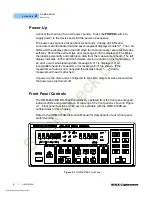
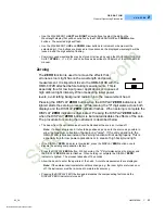
Page 22: ...n is shown on the right display If an error occurs while loading data message E 711 is displayed If an incompatible head is connected error message E 713 is shown If the measurement head is not connected the display shows until a measurement head is attached At power up the main unit is configured to the same state that was present when the power was last turned off Front Panel Controls The OMM 68...

Page 23: ...rror Errors are displayed for three seconds or until the error causing condition is remedied whichever is longer See Appendix A in the OMM 6810B Instruction Manual for a detailed list of error messages Rear Panel Connections The OMH 6722B interfaces with the rear panel of the multimeter as described in the following paragraphs Input Connector The OMH 6722B interfaces the Multimeter via the 26 pin ...

Page 24: ...POWER ANALOG OUT is a non calibrated value between 0 and 10 volts representing the measured power as a percent of full scale power within the selected gain range For example if the full scale power for gain range three is 10 W and the displayed power is 5 000 W then 5 0 volts is present on the POWER ANALOG OUT connector Figure 2 3 Power Analog Out StockC heck com Downloaded from StockCheck com ...

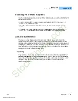
Page 25: ...arm up for at least one hour Beam Alignment Considerations The OMH 6722B is designed to provide a simple operating format The beam from the source should be directed perpendicular to the face of the 6722B and directly into its aperture Be sure the entrance angle does not exceed the specified 10 from perpendicular Be aware that certain lasers emit a significant amount of non lasing radiation This r...

Page 26: ...Focused Beams The OMH 6722B also accepts converging beams In high power applications be sure that the focus of the beam does not occur at the rear of the integrating sphere Again perpendicular beam entry to the Head is required Fiber Optic Cable A fiber optic adapter options AO271 AO272 AO273 and AO276 can be mounted onto the face of the OMH 6722B Measurement Head This threaded ring adapter cap op...

Page 27: ... the DISPLAY ZERO indicator flashes When zeroing is complete the DISPLAY ZERO indicator is illuminated Pressing the DISPLAY ZERO button when the DISPLAY ZERO indicator is illuminated disables the effects of the zero The procedure for zeroing the instrument is described below The beam from the optical source should be blocked at the source or turned off Note If a beam stop is used it should be posi...

Page 28: ...ment in and out of the User Calibration Mode When the LED above the CAL USER button is lighted the unit employs the user defined calibration which has been stored in the Optical Measurement Head Pressing the CAL USER button when the CAL USER LED is lighted causes the instrument to revert to factory calibration and the LED to go out Pressing the CAL SET button while the LED above the CAL USER butto...

Page 29: ...e The design of the Measurement Head is fairly robust however it should be handled with care Stress from dropping the Head or other mishandling could dislodge critical alignments within the Head effectively changing its response and nullifying its calibration It is also sensitive to electrostatic discharge When not in use replace the ESD protective cap that came with the Head on the D connector an...

Page 30: ...O P E R A T I O N Care and Maintenance 14 OMH 6722B C H A P T E R 2 StockC heck com Downloaded from StockCheck com ...

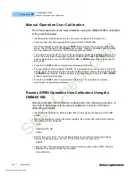
Page 31: ...ne point which changes future power measurements by the percentage calculated during the calibration Recommended Equipment It is recommended that gas line sources not laser diodes be used for calibration Ideal sources include gas lasers such as HeNe at 632 8 nm and spectral lamps with the proper line isolation filters such as a Cesium Lamp and a 845 nm 855 nm interference filter to isolate the 852...

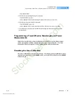
Page 32: ...red power will be shown on the left display Adjust the displayed power to match the laser s known power using the POWER UP and DOWN arrow buttons If large adjustments are necessary hold down the UP or DOWN button to accelerate the change Press the CAL SET button to complete the calibration The unit returns to real time wavelength and power measurements Remote GPIB Operation User Calibration Using ...

Page 33: ...on is complete and the 6810B is performing real time wavelength and power measurements Programming a Fixed Offset to Wavelength and Power Measurements Rather than performing a User Calibration it is possible to enter offset values which are applied to future wavelength and power measurements For more information refer to Chapter 4 of the OMM 6810B Instruction Manual Resetting the User Calibration ...

Page 34: ...C A L IB R A TI O N Resetting the User Calibration 18 OMH 6722B C H A P T E R 3 StockC heck com Downloaded from StockCheck com ...

Page 35: ...lems which may arise during operation A more complete guide including a GPIB troubleshooting guide is provided in Chapter 7 of the OMM 6810B Instruction Manual Troubleshooting Guide If you have difficulty using the 6722B refer to the symptoms listed here Common causes and corrective actions are listed here If problems persist contact your ILX Lightwave representative at 406 586 1244 StockC heck co...

Page 36: ...n the laser s input power exceeds the maximum allowed for the selected gain range Measurements at this level are invalid If in manual mode press the DOWN switch to select the next lower gain range Display shows HI This condition occurs when the instrument interprets the laser s wavelength as greater than 1100 nm which is beyond the capability of the OMH 6722B Display shows LO This condition occurs...

Reviews: