background image

25

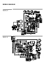
WIRING DIAGRAM

WIRING DIAGRAM

L12...MP

C

K

I

10

16

14

12

9

11

13

15

J

M

P

2

8

6

4

1

3

5

7

C

A

B

E

H

D

2

1

P

M

VT

TS

M

11

11

TT

66

66

66

11

11

11

11

11

66

L1

L2

33

11

R1

22

R3

00

R2

55

R4

44

M

V

S2

S1

2

1

TF

66

66

66

11

11

00

00

00

00

00

00

33

66

66

66

66

66

66

66

66

66

66

00

00

00

33

33

33

00

00

00

00

22

22

00

11

11

11

00

44

44

55

00

00 22 44

11

55

33

TS

K1

2

K1

45

K4

K2

K3

K5

K6

K7

K8

K11

K9

K15

11

66

11

TT

M

M

G

*

66

22

66

22

33

M

MG

L1

33

S1

2

1

C

S2

66

3

2

R3

R1

44

TF

00

66

66

00

00

00

6

4

5

9

7

8

A

B

F

D

I

G

H

1

R2

33

66

00

22

55

00

66

66

00

33

33

66

11

11

11

66

66

11

N2

N1

F3

F2

F1

M

D

U

st

33

M

VT

Summary of Contents for MAJESTIC MILANO 06

Page 1: ...RANGECOOKER INSTALLATION MANUAL ROMA MILANO TORINO MAJESTIC ROMA MAJESTIC MILANO 06 07 08 09 10 12 15 INSTALLATION AND MAINTENANCE EN cod EI33960170000EN 04 2021 ZONA PER TARGHETTA ...

Page 2: ...2 ...

Page 3: ...of cooking Induction cookers GAS INSTALLATION GAS CONNECTIONS By the Qualified installer LPG CONVERSION Replacement of the injectors for all models ADJUSTMENT Adjustments minimun GAS flow Replacement of the injectors oven H3 KITCHEN TABLE ROMA MILANO MAJESTIC ROMA MAJESTIC MILANO Kitchen table TORINO WIRING DIAGRAM Key INDEX 4 5 5 5 6 7 8 8 9 10 11 11 12 12 13 13 14 14 14 17 17 ...

Page 4: ...pected accessories Verify the correct utilization of the appliance use of the oven thermostat and igni tion of the burners Suggest to note the serial number and warranty information Request that a periodic maintenance service has to be carried out at least every two years to maintain a fully functioning appliance In the case of leaking gas close the main gas tap and disconnect the product from the...

Page 5: ...ust system for combustion waste however ILVE strongly recommend that it is installed under a range hood or other smoke extraction system in compliance with the gas safe regulations The knowledge and consultation of the standards are a key factor for a qualified technician Indicatively the amount of air necessary for burner combustion is 2 m3 h for each KW of nominal power installed see plate Shoul...

Page 6: ...r correct ly take the following precautions A Any furniture in the vicinity of the cooker with a height higher than that of the worktop must be at least 50mm from the edge of the cook top B The extractor hood must be installed in the way indicated in its instructions booklet and always at a minimum distance of 650 mm from the top of the hob C If the cooker is installed under a wall unit the minimu...

Page 7: ... back cross bar picture 5 and add 15mm Fix the supporting bracket in the centre of the cooker aperture on the supporting wall Check that the cooker is tight against the back wall to avoid tipping The anti turnover system is assured only if the cooker is installed with the back tight against the back wall INSTALLATION How to install the fixing bracket ...

Page 8: ...itch is able to support the appliance s load see dataplate the power supply should be earthed as per the current regulations The appliance is supplied with a cable This cable must be used for installation The connection must be made taking into account that the green yellow cable is the earth conductor and it must never be interrupted It is necessary that the installation can support the equipment...

Page 9: ...NS Induction cookers POWER SUPPLY CONNECTION CABLE SECTION CABLE TYPE Mod P I06 230V a c 1P N 50 60 Hz 1 phase N 3x4 H05RR Mod P I09 M I09 LBI09 230V a c 1P N 50 60 Hz 1 phase N 3x6 H07RN Mod PDI09 LDBI09 230V a c 1P N 50 60 Hz 1 phase N 3x6 H07RN Mod MDI10 230V a c 1P N 50 60 Hz 1 phase N 3x10 H07RN Mod PDI10 230V a c 1P N 50 60 Hz 1 phase N 3x10 H07RN ...

Page 10: ...n be used to engineer s discretion PIC can be fitted between 180mm 250mm A F F L Gas hose must not be under any strain or tension The gas hose must not touch the floor This will allow the cookers to be fitted with the gas hose running along the base of the cooker This will also mean that the PIC can be connected and disconnected by remo ving the storage drawer and accessing from the front of cooke...

Page 11: ...er fitted in accordance with BS6172 in a position free from excessive heat and potential abrasion from surround items attached to a socket that is firmly fixed to a gas installation pipe and positioned so that the hose hangs freely downwards Never use excessive force to connect or discon nect The hose must be a auto shut off gas hose connected to a PIC b CLASS for LPG installation The cooker must ...

Page 12: ...or the new gas according to table number 2 on page 20 DCC Dual burners unscrew the 2 screws P and remove cover C fig 2 unscrew injectors U using a 7 mm spanner fig 3 fig 4 and replace them with those for the new gas according to table number 1 below 13 LPG CONVERSION Replacement of the injectors for all models 2 1 3 4 U U U ...

Page 13: ...right to decrease it 5 If a liquid gas is used Butane Propane the regulating screw must be fully screwed in 1 Remove the bottom shelf of the oven 2 Light the burner and leave it at maximum for about 10minutes with the oven door closed 3 Turn the knob to minimum and still with the door closed check whether the flames have lowered but are still burning steadily about 3 4 mm 4 Remove the knob of the ...

Page 14: ...ove the burner by removing the screw that secures it 3 Using a 7 mm hose wrench unscrew the injector and replace it with the suitable gas adapter supplied with the appliance See the table below 4 Refit the burner and then the bottom of the oven ADJUSTMENTS Replacement of the injectors oven H3 ...

Page 15: ... 0210 1 37 0332 1 42 0222 1 57 0332 0 72 0306 1 64 0332 1 30 0222 1 48 0332 G25 25 mbar 0 98 0210 1 26 0332 1 35 0222 1 50 0332 0 75 0306 1 50 0332 1 25 0222 1 40 0332 G2 350 13 mbar 1 26 0210 1 64 0332 1 64 0332 2 10 1048 0 91 210 2 10 1048 1 70 0222 1 90 0332 G25 1 25 mbar 0 98 0210 1 25 0309 1 28 0332 1 52 0332 0 71 0306 1 52 0332 1 25 0222 1 43 0332 G25 3 25 mbar 0 94 0210 1 26 0332 1 28 0332 ...

Page 16: ...0101 1 40 0103 G25 20 mbar 1 05 0210 1 37 0332 1 42 0222 1 57 0332 0 72 0306 1 48 0309 G25 25 mbar 0 98 0210 1 26 0332 1 26 0332 1 50 0332 0 75 0306 1 40 0332 G2 350 13 mbar 1 26 0210 1 64 0332 1 64 0332 2 10 1048 0 91 210 1 98 1048 G25 1 25 mbar 0 98 0210 1 25 0309 1 28 0332 1 52 0332 0 71 0306 1 50 0332 G25 3 25 mbar 0 94 0210 1 26 0332 1 24 0332 1 48 0332 0 75 0306 1 40 0332 G110 8 mbar 1 90 02...

Page 17: ...C Temperature probe P Timer Programmer P Timer Clock P1 6 Induction hotplate PE Electric hotplate PT1000 Temperature probe R1 Upper heating element R2 Lower heating element R3 Grill heating element R4 Circular heating element R5 Barbecue heating element R6 Fryer heating element RE Energy regulator S1 Oven warning light S2 Mains power warning light S3 Grill warning light S4 Cooling fun warning S5 B...

Page 18: ...18 HOB GAS BASIC INDUCTION HOB AREA 5 WIRING DIAGRAM MA MA MA MA MA MA MA 11 AA SPL 66 11 11 66 o o o o F N ...

Page 19: ... R2 TS R1 1 1 1 1 1 1 1 1 1 1 66 33 33 44 44 11 11 00 00 22 55 22 55 55 00 00 00 00 00 00 11 11 11 11 11 33 33 66 11 11 11 11 SP NTC LEGENDA SW1 L2 33 M MG 22 22 ET EF S2 S1 P1 P2 66 33 00 SD B C A 66 45 11 CP SS FLC MP P23 DU 11 11 11 33 X13 X14 X10 X9 X15 X3 X4 X2 X1 X5 X6 P1 P2 X1 X2 X200 X201 X1 X2 X200 X201 RE1 RE2 X6 X7 X8 X4 X3 X2 X5 X1 4 X8 X7 11 SP SI SD 66 66 66 66 66 11 11 11 11 11 66 1...

Page 20: ...20 WIRING DIAGRAM INDUCTION HOB AREA 5 INDUCTION HOB AREA 6 ...

Page 21: ...21 WIRING DIAGRAM P 06 07 30 08 09 E3 L 06 09 MP ...

Page 22: ...22 WIRING DIAGRAM WIRING DIAGRAM P 06 07 30 08 09 H3 ...

Page 23: ...M MG L1 L2 M VT M VR R3 22 11 11 66 33 44 44 R4 55 11 TS N F 66 11 K2 K1 K4 K3 K6 45 K5 K15 PT1000 B C A CP MP J3 J6 J4 1 1 1 1 1 J2 J1 J10 1 1 1 P1 P2 P3 J1 1 11 11 11 11 11 00 33 66 66 66 66 66 11 11 11 66 66 55 11 EL1 33 33 BC 00 GND 11 11 SD L TCT N IGN E V ION NTC LED 11 AA SA EN IN OUT OI 22 00 00 00 00 00 22 22 22 22 22 00 ...

Page 24: ...X2 X5 X1 4 X8 X7 11 SP SI SD 66 66 66 66 66 11 11 11 11 11 66 11 45 45 EN TT 66 LEGENDA J11 SP J12 J16 J10 J7 J8 J9 J6 J5 J4 J3 J2 J1 J14 J13 J15 1 1 1 1 1 1 1 1 1 M MG L1 L2 M VT M VR R3 22 11 11 66 33 44 44 R4 55 11 TS N F 66 11 K2 K1 K4 K3 K6 45 K5 K15 PT1000 B C A CP MP J3 J6 J4 1 1 1 1 1 J2 J1 J10 1 1 1 P1 P2 P3 J1 1 11 11 11 11 11 00 33 66 66 66 66 66 11 11 11 66 66 55 11 EL1 33 33 BC 00 GND...

Page 25: ... 1 TF 66 66 66 11 11 00 00 00 00 00 00 33 66 66 66 66 66 66 66 66 66 66 00 00 00 33 33 33 00 00 00 00 22 22 00 11 11 11 00 44 44 55 00 00 22 44 11 55 33 TS K12 K1 45 K4 K2 K3 K5 K6 K7 K8 K11 K9 K15 11 66 11 TT M MG 66 22 66 22 33 M MG L1 33 S1 2 1 C S2 66 3 2 R3 R1 44 TF 00 66 66 00 00 00 6 4 5 9 7 8 A B F D I G H 1 R2 33 66 00 22 55 00 66 66 00 33 33 66 11 11 11 66 66 11 N2 N1 F3 F2 F1 M DUst 33 ...

Page 26: ...26 WIRING DIAGRAM LD 09 10 MP M12 E3 ...

Page 27: ...2 J1 J10 1 1 1 P1 P2 P3 J1 1 11 11 11 11 11 11 11 33 00 33 00 66 66 66 66 66 11 11 11 66 66 55 11 11 11 11 11 11 JP2 JP1 1 1 JP3 1 JP5 JP6 JP4 1 1 PT1000 DU M MG L2 11 SD SE 11 11 11 11 66 66 33 00 33 M VR 11 33 SA X13 X14 X10 X9 X15 X3 X4 X2 X1 X5 X6 P1 P2 X1 X2 X200 X201 X1 X2 X200 X201 RE1 RE2 X6 X7 X8 X4 X3 X2 X5 X1 4 X8 X7 11 SP SI SD 66 66 66 66 66 11 11 11 11 11 66 11 45 45 11 66 66 EN NTC ...

Page 28: ...1 P1 P2 P3 J1 1 11 11 11 11 11 11 11 33 00 33 00 66 66 66 66 66 11 11 11 66 66 55 11 11 11 11 11 11 JP2 JP1 1 1 JP3 1 JP5 JP6 JP4 1 1 PT1000 DU M MG L2 11 SD SE 11 11 11 11 66 66 33 00 33 SA X13 X14 X10 X9 X15 X3 X4 X2 X1 X5 X6 P1 P2 X1 X2 X200 X201 X1 X2 X200 X201 RE1 RE2 X6 X7 X8 X4 X3 X2 X5 X1 4 X8 X7 11 SP SI SD 66 66 66 66 66 11 11 11 11 11 66 11 45 45 11 11 11 66 66 66 EN NTC MP R3 22 00 R2 ...

Page 29: ... 44 66 S2mf Vmf L2 11 33 M VTst 66 66 66 ET st 11 EFmf P P36 NTC st EF st 33 11 11 R3 st R1 st R2 st 66 11 66 11 L1 00 66 66 66 33 00 55 11 M MG 66 22 22 44 M MG st L1 st TS st 44 44 22 22 22 22 00 00 00 00 00 33 33 33 00 00 11 11 11 11 11 11 11 11 11 11 66 66 66 66 66 66 S2st 66 33 S1st 00 00 K7 K9 K13 K11 K15 K8 B C A 66 45 11 CP SS FLC MPmf MPst P23 DUmf DUmf 11 DUst 00 11 66 66 33 33 M VTmf 11...

Page 30: ...WIRING DIAGRAM P15 E3 ...

Page 31: ...WIRING DIAGRAM PD 09 10 I E3 PD 09 10 E3 ...

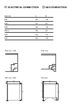
Page 32: ...CONNECTION Rear view M30 Side view M30 Rear view Side view Mod mm M07 M30 M09 MD10 M12 M15 A 205 120 190 140 150 195 B 130 80 140 95 110 150 E G 370 120 A B 60 40 890 30 20 15 700 E G 200 100 A B 60 740 40 140 920 30 15 700 E G ...

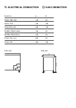
Page 33: ... CONNECTION Mod mm P06N P06 L06 P07N P07 P09N P09 L09 PD09N PD09 LD09 PD10N PD10 LD10 P12N P12 L12 P15N P15 Rear view Side view A 130 190 240 140 140 225 200 B 80 150 150 80 80 90 135 E G 230 90 A B 60 35 55 600 40 860 920 E G ...

Page 34: ...NOTES ...

Page 35: ......

Page 36: ...IMPORTER KitchenEX Limited MBP5 Meadowhall Business Park Carbrook Hall Road Sheffield South Yorks S9 2EQ United Kingdom 44 114 399 8672 ...

Reviews: