


28
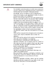
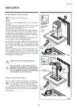
The fastening kit (screws and plugs) supplied with the hood
can only be used on masonry wall. For installation on other
types of walls consider alternative fastening systems,
taking into account the strength of the wall itself and the
weight of the hood.
To perform the installation and ensure the best solidity of
the whole framework, always use the the securing devices
and the components (e.g. screws, bolts, brackets, etc.)
provided with the packaging;
In order to prevent any loss in the product efficiency and
safety of use, the hood should be installed indoor only,
sheltered from weathering (i.e., rain, wind) and harsh
environmental conditions (dried salt, extreme thermal
excursion);
Do not change the electrical, mechanical and functional
structure of the equipment.
The electric connection socket must be easy to reach
even after installation of the equipment.
Should this not be the case, a general switch must be
installed, in order to disconnect the
hood from the power supply in case of need.
The maximum weight of any objects placed on top of the
hood or attached to the same should not exceed 2 kg
(4,4 lb).
The air must not be discharged into a flue that is used for
exhausting fumes from appliances burning gas or other
fuels.
Do not hang on the equipment, and do not use it as a
support for other objects or cabinets.
Any variation or operation in the electrical system should
be performed exclusively by a qualified electrician;
Do not repair the hood by yourself nor replace any of its
components, except for the antigrease and the carbon
filters. Repairs and other work performed by unqualified
personnel will nullify any warranty right on the product, and
could lead to product failure and damage to people or
property.
IMPORTANT SAFETY WARNINGS
Summary of Contents for AGK Series
Page 2: ......
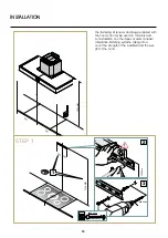
Page 19: ...19 INSTALLER STEP 3 OK 2 1 INSTALLATION ...
Page 20: ...20 STEP 4 STEP 5 1 1 ø8 mm ø 05 16 2 NON FORNITA 2 3 INSTALLATION ...
Page 21: ...21 INSTALLER STEP 6 STEP 7 1 3 4 2 2 3 1 ø8 mm ø 05 16 40 mm 137 64 INSTALLATION ...
Page 22: ...22 STEP 8 STEP 9 INSTALLATION ...
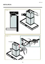
Page 23: ...23 INSTALLER INSTALLATION STEP 10 STEP 11 150 mm 3 3 4 2 1 2 ...
Page 24: ...24 INSTALLATION STEP 12 STEP 13 2 3 4 1 ø8 mm ø 05 16 40 mm 137 64 ...
Page 25: ...25 INSTALLER INSTALLATION STEP 14 1 STEP 15 2 ...
Page 26: ...26 INSTALLATION STEP 16 2 1 ...
Page 32: ......


