


12
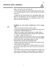
CLEANING AND MAINTENANCE
GREASE METAL FILTERS
These filters are usually made in aluminium or stainless
steel, and their main purpose is to block the particles of oil
and fat suspended in the cooking fumes.
An excessive accumulation of grease inside the filters
could cause unpleasant smells and decrease the suction
power of the hood. Please note that accumulated fat is
highly flammable: any fire could lead to severe damage to
both users and the product.
For these reasons, the anti-grease filters should be washed
at least
once a month
, immersing them into hot water and
dish soap for at least one hour.
Rinse with plenty of water and wait for the filters to be fully
dry before putting them back in place.
Please note that the maximum temperature is
70°C/158°F
:
higher temperature can cause darkening in the metal
(please note that this DOES NOT impair the operation of
the filter).
For their removal see
Fig. 5
.
ACTIVE CARBON FILTERS
These filters cannot be washed or regenerated, and should
therefore be replaced every 3 to 4 months, depending on
the hood usage. Damp environments, high temperature,
soiled anti-grease filters and the use of an induction hob
could result into an accelerated decay of the filters.
There are two different kind of carbon filters:
- a rectangular one (similar to the metallic anti-grease filter,
it can be removed by simply pulling the handle);
- a rounded one (usually secured to the blower, it can be
removed by counter-clockwise twisting).
For the instructions on carbon and anti-grease filters
removal, see
Fig. 6
.
Internal recirculation hoods have to be used only with
active carbon filters installed.
1
2
Fig.6
A
C
B
Summary of Contents for AGK Series
Page 2: ......
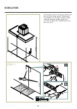
Page 19: ...19 INSTALLER STEP 3 OK 2 1 INSTALLATION ...
Page 20: ...20 STEP 4 STEP 5 1 1 ø8 mm ø 05 16 2 NON FORNITA 2 3 INSTALLATION ...
Page 21: ...21 INSTALLER STEP 6 STEP 7 1 3 4 2 2 3 1 ø8 mm ø 05 16 40 mm 137 64 INSTALLATION ...
Page 22: ...22 STEP 8 STEP 9 INSTALLATION ...
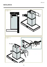
Page 23: ...23 INSTALLER INSTALLATION STEP 10 STEP 11 150 mm 3 3 4 2 1 2 ...
Page 24: ...24 INSTALLATION STEP 12 STEP 13 2 3 4 1 ø8 mm ø 05 16 40 mm 137 64 ...
Page 25: ...25 INSTALLER INSTALLATION STEP 14 1 STEP 15 2 ...
Page 26: ...26 INSTALLATION STEP 16 2 1 ...
Page 32: ......


