iLumin SI-2 Installation Manual Download Page 9

P

7

Startup action

The Startup Actions tab allows you to optionally arrange 
for a particular action to be instigated every time that the 
SI-2 unit is powered on.

To choose a startup action

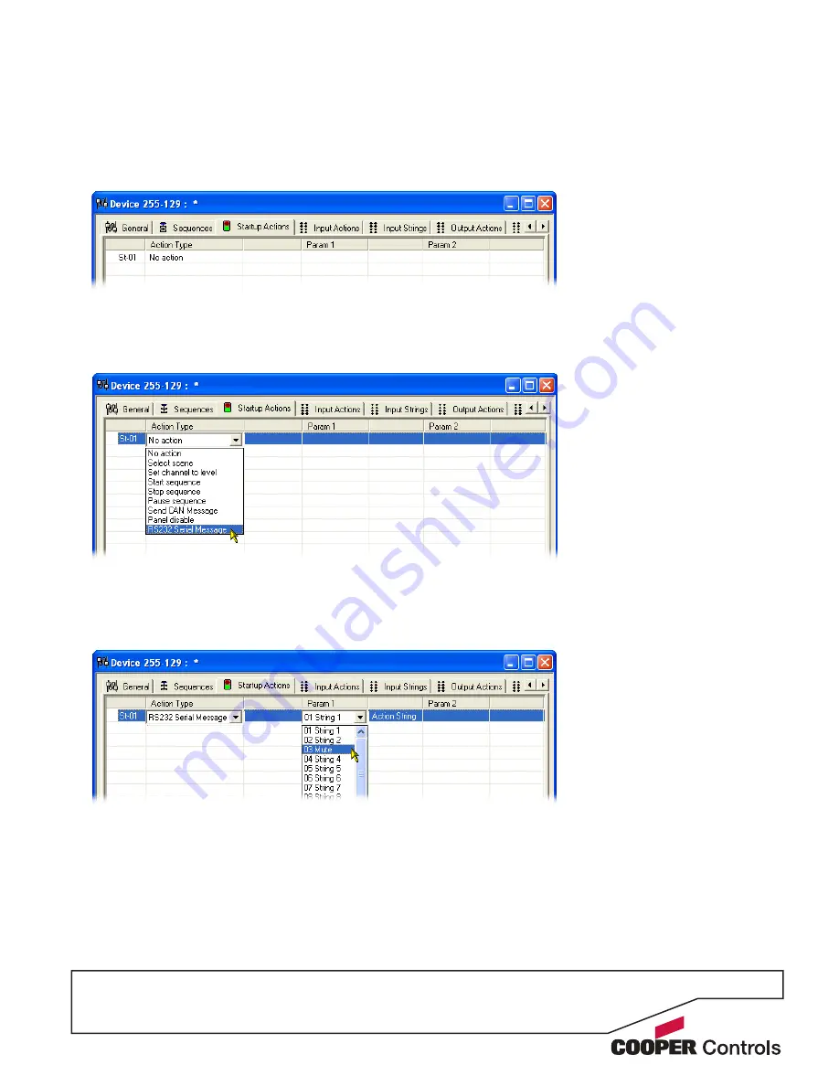
1  Click on the ‘Startup Actions’ tab to display the  

following page:

2  Click on the first entry to highlight it and also to show 

selection box for the ‘Action Type’ column. Click 
on the ‘Action Type’ down arrow to reveal the list of 
available options:

3  Select the required action type. Depending upon the 

chosen action, one or more of the ‘Param’ columns 
to the right will show their own selection options. You 
can use these to further define the action that should 
occur during the SI-2 startup phase.

  Note: When selecting the RS232 Serial Message 

option, the available output message strings can be 
viewed and altered within the ‘Output Strings’ tab.

4  When all settings have been made, either click the 

Apply button to save without closing the window or 
click the OK button to save and close.   


Summary of Contents for SI-2

Page 1: ...SI 2 System Integrator Installation guide S I 2 N A...

Page 2: ......

Page 3: ...termination 3 Serial device connection 4 Operation indicators 4 Programming 5 Adding the SI 2 to iCANsoft 5 The SI 2 configuration window 5 Viewing SI 2 details in iCANsoft 5 RS232 communication setti...

Page 4: ...2 also monitors messages being sent back from the connected serial device and when any of those messages match those stored within its memory a range of actions can be triggered on the iCANnet network...

Page 5: ...tion to the serial device is treated separately and has no impact on whether or not the SI 2 should be terminated To disable SI 2 termination move the jumper from the lower two pins to the upper two p...

Page 6: ...ate 1200 2400 4800 9600 19200 38400 57600 or 115200 Data bits 7 or 8 Stop bits 1 or 2 Parity None Reserved Even or Odd Handshaking Enabled or Disabled TxD pin 2 RxD pin 3 CTS pin 7 GND pin 5 RTS pin 8...

Page 7: ...thin the iCANsoft main window select Tools Advanced Network Search or On the SI 2 unit adjacent to the green connector block press and release the small button to cause an announcement message to be s...

Page 8: ...either click the Apply button to save without closing the window or click the OK button to save and close Use this section to ensure that the SI 2 communication settings match those of the connected...

Page 9: ...wn arrow to reveal the list of available options 3 Select the required action type Depending upon the chosen action one or more of the Param columns to the right will show their own selection options...

Page 10: ...or field on the right enter or edit the message string as necessary 4 When the message is complete click the OK button to return to the Input Strings page 5 Within the Input Strings page you can enter...

Page 11: ...the Action Type down arrow to reveal the available actions 3 Select the required action Depending upon the chosen action one or more of the Param columns to the right will show their own selection op...

Page 12: ...t from cursor field on the right enter or edit the message string as necessary 4 When the message is complete click the OK button to return to the Output Strings page 5 Within the Output Strings page...

Page 13: ...ing upon the chosen action one or more of the Param columns to the right will show their own selection options You can use these to further define the iCANnet action that will be used to trigger the m...

Page 14: ...quence then both events will take place simultaneously To define a sequence 1 Click on the Sequences tab to display the page 2 Right click within the main panel area to display a popup menu Select th...

Page 15: ...string to be sent to the serial device Output Strings allows you to send any of the programmed output strings to the serial device independently of the triggering iCANnet action Startup Action launche...

Page 16: ...convert Virtual Control Messages between the network and the con nected device Virtual control messages are used to control the system as whole not individual devices These message conversions are ha...

Page 17: ...0 to 999 Channel 0 affects ALL channels in an area Axxx defines the Area Number valid for 1 to 999 Command SF Stop Fade This message stops fading in an area The syntax is SFxxx Axxx cr SFxxx defines...

Page 18: ...damage during shipment or by improper service There are no warranties which extend beyond the hereinabove limited warranty INCLUDING BUT Cooper Controls 203 Cooper Circle Peachtree GA 30269 800 553 38...

Reviews: