background image

1199

DDIIFFFFU

USSEERR ##00558811..33

The white diffuser can be secured to the front of the DS200 when softer lighting or

coverage greater than 100° is desired. The diffuser reduces the strobe output by one full

f-stop while increasing the coverage angle to 110°.

D

DIIFFFFU

USSEERR IIN

NSSTTAALLLLAATTIIO

ON

N ________________________________________________________________________________________

1. The diffuser features three protruding ears for use in installation and removal.

The protruding ears on the diffuser should be positioned away from the strobe.

2. Note the three cutouts around the perimeter of the diffuser and the three tabs

inside the perimeter of the DS200 front. Place the diffuser over the front of the strobe,

and rotate the diffuser so that the cutouts align with the tabs on the front. Insert the

diffuser thru the tabs, and then rotate the diffuser so the tabs on the front lock the

diffuser in place.

3. To remove the diffuser, rotate the diffuser so the cutouts align with the tabs on

the front. Grasp the protruding ears on the diffuser to remove.

4. A lanyard can be attached to the diffuser by threading it thru the two circular

openings on the diffuser.

U

USSEE O

OFF TTH

HEE D

DIIFFFFU

USSEERR______________________________________________________________________________________________

The diffuser reduces the light intensity by one full f-stop. When referencing the

exposure guide information on the previous page, reference one less f-stop (one number

greater) when the diffuser is secured to the DS200.

For the TTTTLL//AAuuttoo eexxaam

mppllee with ISO 100 film, if you select f-8 w

wiitthhoouutt the

diffuser, you can shoot subjects up to 1.5m (5’) away as stated on the previous page.

If you aadddd tthhee ddiiffffuusseerr to the strobe with the camera set at f-8, then reference one

less f-stop (one number greater) than f-8 which is f-11, meaning you can shoot

subjects up to 1m (3.6’) away.

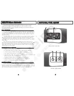
Substrobe 200 Front

Protruding Ear

Holes for Lanyard

Cut-out

+

+

+

Flash Diffuser

Flash Tube

Tab

Modeling Light

2200

M

MO

OU

UN

NTTIIN

NGG TTH

HEE SSTTRRO

OBBEE

IIKKEELLIITTEE AARRM

M SSYYSSTTEEM

MSS ______________________________________________________________________________________________

Ikelite offers several arm choices compatible with the DS200. The arm is NOT

supplied with the strobe unless purchased as part of a complete package.

Ikelite arm systems are designed for underwater use and may not hold the

adjustment ABOVE WATER due to the weight of some large strobes. Be careful when

transporting the system since some camera trays may not be able to support the weight

of the strobe above water.

SSTTRRO

OBBEE M

MO

OU

UN

NTT ________________________________________________________________________________________________________

The strobe features either a paddle-type

or bbaallll--ttyyppee mount. Purchased as an individual

strobe, the standard paddle-type mount is

featured as pictured to the right. The rubber

gasket on the strobe mount creates friction

against the arm and should NOT be lubricated.

If the DS200 strobe is purchased as an

Ikelite package, then the Ikelite ball-socket

arm with ball-type mount is featured instead

of the standard paddle-mount.

TThhee ccoonnttrrooll ppaanneell oonn tthhee D

DSS220000 ssttrroobbee rreem

maaiinnss vviissiibbllee rreeggaarrddlleessss ooff

w

whheetthheerr tthhee ssttrroobbee iiss m

moouunntteedd ttoo tthhee lleefftt oorr rriigghhtt ooff tthhee ccaam

meerraa..

Any Camera System 

#4085.26 Arm on DSLR Housng 

Stem Mount 

Tray Mount 

Wing Nut

Rubber
Gaskets

Ikelite

Substrobe

N5 Tray

Wing Nut

Washer

Center
Cap

Ball 
Clamp

Large
Wing
Nut

Universal  
Tray

Wing Nut

Washer

Large
Wing
Nut

Large
Wing
Nut

Center
Cap

Center
Cap

Quick Grip
Handle

11

16

22

32

8.0

4.0

5.6

25

5

0

10

0

200 400 8

00

A

S

A

/

IS

O

F

1/2

1/4

1/8

M

3

2.3

1.5

1

.75

.5

.38

1.2

5

1.8

10

2.5

3.6

5

7

FT

Wing Nut

Washer

Handle

Tray

N5 Tray

for Nikonos

Universal Tray for

Nikonos III, IV, V

or Motormarine II

SLR Tray

Summary of Contents for DS-200

Page 1: ...mm SLR with diffuser G Gu ui id de e N Nu um mb be er r I IS SO O 1 10 00 0 f fe ee et t 76 surface 38 underwater G Gu ui id de e N Nu um mb be er r I IS SO O 1 10 00 0 m me et te er rs s 24 surface 12 underwater F Fi ir ri in ng g M Mo od de es s TTL Auto Manual 1 2 M 1 4 M 1 8 M Slave featuring auto exposure using optional DS Sensor 4100 5 Slave featuring 10 manual power settings using optional ...

Page 2: ... capacity Aim the DS200 and illuminate your subject s colors with the built in modeling light night diving light O OV VE ER RV VI IE EW W O OF F D DS S2 20 00 0 F FE EA AT TU UR RE ES S _ __ __ __ __ __ __ __ __ __ __ __ __ __ __ __ __ __ __ __ __ __ __ __ __ __ __ __ __ __ __ __ __ __ __ __ __ _ Separate power and firing mode switches Interchangeable battery pack features industrial grade NiMH ba...

Page 3: ...maining For general guidelines refer to the following list 3 LED s above 75 2 LED s above 50 1 LED above 25 No LED less then 25 F FI IR RI IN NG G M MO OD DE E S SW WI IT TC CH H_ __ __ __ __ __ __ __ __ __ __ __ __ __ __ __ __ __ __ __ __ __ __ __ __ __ __ __ __ __ __ __ __ __ __ __ __ __ __ __ __ __ __ __ __ __ __ _ Multiple firing modes are featured TTL Auto and four manual power settings Full ...

Page 4: ...screwdriver counter clockwise 90 and then lift off external section of the door Reverse the procedure to resecure the two battery door sections Keep o ring and sealing surfaces clean LIGHTLY LUBRICATE the o ring with the silicone lubricant provided Also lightly lubricate o ring sealing surface on the inside of the strobe body Use only enough lubricant to lightly cover the o ring wipe off any exces...

Page 5: ...HE E S ST TR RO OB BE E _ __ __ __ __ __ __ __ __ __ __ __ __ __ __ __ __ __ __ __ __ __ __ __ __ __ __ __ __ __ __ __ __ __ __ __ __ __ __ __ __ __ __ __ __ __ __ __ _ Use the modeling light to aim the strobe Look thru the camera s viewfinder and aim the strobe so that the modeling light shines in the center of your picture area If your subject distance greatly changes you should recheck the posi...

Page 6: ...ash compatible and provides optimum performance with traditional film cameras digital still cameras and dSLR cameras in related Ikelite housings The DS200 strobe is compatible for eTTL and iTTL with the Ikelite housing system The appropriate sync cord or sensor must be connected to trigger the DS200 strobe The TTL Auto exposure mode on the Ikelite DS200 strobe is compatible with the following TTL ...

Page 7: ... Auto exposure signal from the camera to the strobe Please review the Compatible Camera section on the previous page for additional information T TT TL L S SY YN NC C C CO OR RD DS S _ __ __ __ __ __ __ __ __ __ __ __ __ __ __ __ __ __ __ __ __ __ __ __ __ __ __ __ __ __ __ __ __ __ __ __ __ __ __ __ __ __ __ __ __ __ __ __ __ __ __ __ _ Ikelite offers interchangeable sync cords so that different ...

Page 8: ...rd ends are identical either end can be connected to the strobe 3 Hand tighten the knurled retaining ring on the cord Push the connector body further into the bulkhead connector and continue to tighten the knurled ring L LU UB BR RI IC CA AN NT T Use only Ikelite brand silicone lubricant with Ikelite brand o rings as other brand lubricants can cause the Ikelite o rings to swell in size D DO O N NO...

Page 9: ...SLR cameras do not offer TTL compatible circuitry so only manual exposure is offered for the Ikelite Substrobes Select the non TTL Nikonos cord 4104 31 or 4104 32 for compatibility when connecting to the Nikonos style female socket on the non Ikelite housing Follow the procedure referenced above to connect the Nikonos cord to the housing 1 18 8 E EX XP PO OS SU UR RE E G GU UI ID DE E The purpose ...

Page 10: ... f 11 meaning you can shoot subjects up to 1m 3 6 away Substrobe 200 Front Protruding Ear Holes for Lanyard Cut out Flash Diffuser Flash Tube Tab Modeling Light 2 20 0 M MO OU UN NT TI IN NG G T TH HE E S ST TR RO OB BE E I IK KE EL LI IT TE E A AR RM M S SY YS ST TE EM MS S _ __ __ __ __ __ __ __ __ __ __ __ __ __ __ __ __ __ __ __ __ __ __ __ __ __ __ __ __ __ __ __ __ __ __ __ __ __ __ __ __ __...

Page 11: ...the receptor Release the button and it should spring back to the original position locking the arm in place An optional longer stem 9577 33 can be purchased separately to replace the original short stem on the Digital Arm if a convenient mounting location is needed to secure the optional Ikelite DS Sensor or EV Controller T Tr ra ay y M Mo ou un nt t The Ikelite tray mount is provided with the arm...

Page 12: ...exposure is preferred choose the optional Ikelite EV Controller 4100 6 which provides 10 manual power settings in half stop increments The EV Controller can be triggered using the built in slave sensor or an optional sync cord can be connected Always carry spare batteries Weak batteries cause many camera and strobe problems Prolong the battery life by recharging the NiMH monthly even when not used...

Page 13: ... other photographic equipment In addition to normal procedures we strongly recommend that this strobe be returned to Ikelite periodically to be checked and pressure tested 1 We suggest storage of your Substrobe with the battery door removed to allow any hydrogen air mixture to escape 2 Always rinse the exterior of the Substrobe with fresh water after use The strobe can be cleaned by soaking it in ...

Page 14: ...ncluding but not limited to bulb failure are not covered Except as mentioned above no other warranty expressed or implied applies to this Ikelite product We recommend adding an ALL RISK floater to your homeowner s insurance policy in the event you damage flood or lose your camera or strobe Ikelite warranty does NOT cover customer neglect R RE ET TU UR RN NI IN NG G P PR RO OD DU UC CT TS S F FO OR...

Reviews: