background image


*  Terminate the output from RGB OUT and VIDEO OUT at 75ohms on the receiver side. 
 
*  FOOT SW to be connected to this device, it conforms to the IEC60601-1

2005 

 
*  Equipment connected to this unit except FOOTSW that conform to IEC standards that 

apply to the equipment or IEC60601-1:2005 

 
*  If you are connecting to a device that is in contact with the patient to make the 

connection in accordance with IEC60601-1

2005 Annex I Table I.1 

 
*  While connected, it is necessary to fit the evaluation and IEC60601-1

2005 Section 

16. 

 
*  When FOOT SW is used in the operating room, you should always use the FOOT SW 

which is conformed to the IEC60529-IP6. 

 
*  When FOOT SW is used beside the operating room, you should always use the FOOT 

SW the IEC60529- IP1. 


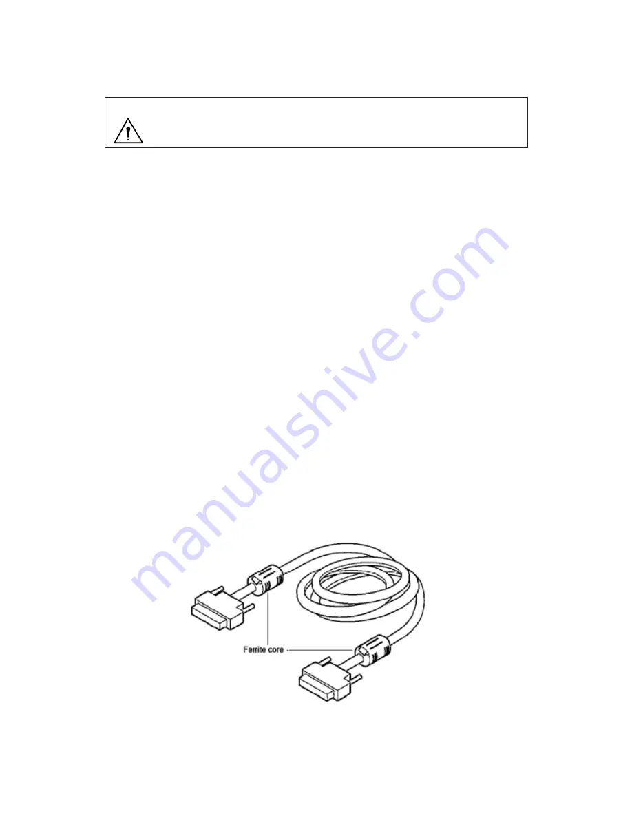
DVI connector 

This connector outputs a digital signal. Connect a DVI cable to this connector. 


* Use a DVI cable with a ferrite core at both ends. Contact Ikegami if you are unable 

to obtain such a cable. 

Precautions During Connection 

- Before connection, always power OFF the camera. 

- The dedicated camera head should be connected. The other head should 

not be connected; otherwise, a failure will occur

.


CAUTION: 

Summary of Contents for MKC-750UHD

Page 1: ...MKC 750UHD Digital Process Compact 3CMOS Color Camera Operation Manual...

Page 2: ...The software that we have manufactured is copyrighted by IKEGAMI TSUSHINKI CO LTD You may not reproduce or alter it in whole or in part without permission...

Page 3: ...ter spills in the unit a fire or electric shock maybe caused Do not use other power supply voltage than specified A fire or electric shock may be caused Do not put a metal body or flammable material i...

Page 4: ...iceman exchanges it is possible parts AC cable When exchanging an AC cable of an accessory When installing the unit Avoid installing the unit in a moist place dusty place or any other place exposed to...

Page 5: ...n for help Changes or modifications not expressly approved by the party responsible for compliance could void the user s authority to operate the equipment Please classify by the material and dispose...

Page 6: ...onment If the user of the MODEL MKC 750UHD requires continued operation during power mains interruptions It is recommended that the MODEL MKC 750UHD be powered from an uninterruptible power supply or...

Page 7: ...as determined by an electromagnetic site survey ashould be less than the compliance level In each frequency range b Interference may occur in the vicinity of equipment marked with the following symbol...

Page 8: ......

Page 9: ...djusting an AE Level 22 Outputting a Still Image 23 Outputting Color Bars 24 Selecting a Scene File 25 4 Menu Operation 26 Operation Method 26 Exposure 27 LEVEL 29 DTL 30 Color 31 Scene File 33 Functi...

Page 10: ...4 2 Saving a set data 47 5 4 3 Loading a set data 48 3D support function 49 5 5 1 Connections and settings 49 5 5 2 Linkage the operation panel and the menu 51 6 Default Settings 52 Exposure 52 Level...

Page 11: ...s 3840 x 2160 Full HDTV format with 1600TV lines horizontal resolution S N ratio with 56dB In addition to the 4K output signal the output of HD SDI corresponding to 3G DVI system is available at the s...

Page 12: ...0A 7R 4S 12V GND IRIS N C Camera connector The camera connector of a dedicated camera cable is connected here Please be aware that the camera connector is different in size between the camera head sid...

Page 13: ...ectronic shutter speed automatically and adjusts to the most suitable output level Automatic sensitivity button This button controls automatically a sensitivity setting inside the camera and adjusts t...

Page 14: ...s adjust the brightness of a video Arrow keys This is used for selecting the scene file and operating menu Function button The function key set to F1 F4 is executed Page 36 Freeze button This freeze a...

Page 15: ...ption is required for connection HD SDI 3G SDI OUT connector 2 lines An HD SDI 3G SDI input compatible monitor etc is connected here The same video is output to two lines A coaxial cable with a 75 imp...

Page 16: ...nization with other products I am afraid that I can not guarantee Equipotential terminal This is used to make the potential of a cabinet equal to other equipment Camera connector The camera connector...

Page 17: ...operation manual that comes with the monitor Always please use the supplied power cable in the connection with the power supply 4K Compatible monitor MKC 750UHD camera head Foot switch Camera cable D...

Page 18: ...it the evaluation and IEC60601 1 2005 Section 16 When FOOT SW is used in the operating room you should always use the FOOT SW which is conformed to the IEC60529 IP6 When FOOT SW is used beside the ope...

Page 19: ...duct on the side of the CCU Placed away 1 5cm or more from the wall so as not to block the ventilation ducts Set up blocking the ventilation holes is cause of failure Placed away 1 5cm or more from th...

Page 20: ...750UHD is set to the normal shooting state Before relocating the main unit always turn off the main power remove the power plug and disconnect the cables connected among equipment If any cable is dis...

Page 21: ...gely and press the white balance button During automatic adjustment the white balance button lights up AWB will appear on a monitor screen When the adjustment is complete successfully AWB COMPLETED wi...

Page 22: ...When the automatic adjustment is complete the light of the auto white button will go out automatically...

Page 23: ...to carry out fine adjustment of the red level and blue level density of picture as desire of user Operation Turn the color correction volume red and the one blue to make adjustments z Turning it to t...

Page 24: ...vel A screen becomes easy to see by raising the level when the screen is too dark or reducing it when too bright This function is enabled when GAIN Electronic shutter is AUTO Operation Turn the bright...

Page 25: ...ut and switch to freeze frame output Operation Press the freeze button A still image will be output immediately While a still image is output the freeze button lights up To unfreeze the image press th...

Page 26: ...itor brightness contrast etc Operation Press the color bar button Color bars will be output immediately While color bars are output the color bar button is lit in green To restore a video from the cam...

Page 27: ...tored Loading The arrow key corresponding to the currently selected scene file is lit Select a scene file with the arrow key The numeral near an arrow key shows a scene file number The arrow key corre...

Page 28: ...ont to select the item and then press the keys or the SET button to enter the submenu screen Change with the keys to set value of each setting item Use the keys to return to the previous menu When wit...

Page 29: ...ol or Gain Control is AUTO fine adjust a shutter speed according to the level that is set here 128 127 If the screen is too dark the value is increased and if the screen is too bright the value is dec...

Page 30: ...k subject is picked up you can adjust the brightness AUTO According to the brightness of a video input a gain will automatically be adjusted so that an output level may always be fixed Base Sets the o...

Page 31: ...kes a bright image more visible ON Enable a setting OFF Disable a setting R Paint Adjusts the red level This is the same function as paint adjustment volume on the front of the CCU 128 127 Increasing...

Page 32: ...Adjusts the detail enhancement level 0 31 Increasing the value results in a sharper image Boost Sets the boost frequency for detail enhancement 2 16MHz The lower the value the easier it is to carry o...

Page 33: ...Manual Manual adjustment of white balance R Gain Adjusts the red gain B Gain Adjusts the blue gain Chroma Set the color intensity 128 127 The higher the value the more intense the color The lower the...

Page 34: ...OFF Disable an adjustment ON Enable an adjustment...

Page 35: ...ription Scene Number Select the set scene file read it Store Scene Store the set condition in the scene file Select the scene file you wish to set and press the SET button Initialize Scene Select the...

Page 36: ...and vertical inversion of the image OFF The both horizontal and vertical direction become the normal rotation output H FLIP Outputs a horizontally inverted image V FLIP Outputs a vertically inverted...

Page 37: ...s operated nothing is carried out FREEZE Outputs a still images Operate the foot switch again to return to moving images SCENE F ROT Switches the scene file selection H FLIP Outputs a horizontally inv...

Page 38: ...the function key is operated NONE Nothing is carried out even when the function key is operated H FLIP Outputs a horizontally inverted image V FLIP Outputs a vertically inverted image ROTATE Outputs...

Page 39: ...cts the DVI output signal output format 1080p Outputs the progressive signal 1080i Outputs the interlace signal H Position 32 32 Adjusts the horizontal display position of a screen in one pixel unit V...

Page 40: ...orizontal phase for Genlock input V Phase Adjusts the vertical phase for Genlock input 3D Support When the 3D system is configured sets whether to operate as a slave or as a master Center Maker Displa...

Page 41: ...ate and time can be set Item Setting Description Year Sets the date and time Month Day Hours Minutes Seconds Setting Date Time Year 2016 Month 3 Day 2 Hours 11 Minutes 34 Seconds 20 Setting READY 2016...

Page 42: ...READY START SET All the settings other than those for scene files will be initialized USB Memory Read and store of a USB memory can be NO MEDIA USB memory is not inserted READY USB memory is inserted...

Page 43: ...Information The version information of the software appears Information CCU Firmware V1 00 6162 CCU FPGA V1 00a 6155 Head FPGA V5 00e 6153...

Page 44: ...external synchronization mode from internal synchronization mode automatically SYNC input conditions 3 value SYNC 0 6 Vp p 75 5 1 1 Wiring Example Prepare two sets of the CCU and camera for MKC 750UHD...

Page 45: ...ly Setting a Metering Frame You can change the range of a metering frame as desired By adjusting a metering frame a video can automatically be adjusted in keeping with the use environment 5 2 1 Settin...

Page 46: ...ton to nish setting Setting the Position Select Position and press the SET button to adjust the position of a metering frame The frame size is not changed Use the keys to adjust the position Setting t...

Page 47: ...menu Since the present setting is saved in the scene le set beforehand to the setting you wish At Scene File on a menu select one of the alternatives Store Scene 1 to Store Scene 4 and press the SET b...

Page 48: ...Precautions on USB memory When USB memory is inserted the LED in the maintenance door is light up And USB Memory state of Others is changed from NO MEDIA to READY USB memory equipped with a protective...

Page 49: ...e power while it is displayed as USB Memory Busy When an USB memory is removed while being accessed or equipment is powered off a data of USB memory may get corrupted A USB memory that a free space ha...

Page 50: ...and the item of USB Memory returns to READY Reading take about 30 sec Don t remove the USB memory or turn off the power while it is displayed as USB Memory Busy When an USB memory is removed while bei...

Page 51: ...wo machines 5 5 1 Connections and settings The 3D system of this machine is constructed one master machine one slave machine and 3D adaptive monitor Please connect each apparatus like a lower figure C...

Page 52: ...he master it is no problems check the Specification of the monitor for the connection of the output of the left and right of the camera Turn ON the main power switch It s possible even from the left o...

Page 53: ...e connection always power OFF the camera 5 5 2 Linkage the operation panel and the menu When the setting is finished White balance Auto shutter Auto sensitivity Auto Iris and Set value of each volume...

Page 54: ...it 1 4000 1 100 1 10000 Slow Shutter DISABLE ENABLE DISABLE Slow Shutter Limit 1 15 1 4 1 30 Gain AUTO MANUAL Normal Gain 6dB 9dB 24dB AUTO Base 6dB 9dB 6dB Limit 9dB 3dB 18dB Line Mix OFF ON OFF Iris...

Page 55: ...B ATW MANUAL R Gain 0 128 127 B Gain 0 128 127 Chroma 0 128 127 Matrix OFF OFF ON R G 0 170 342 R B 0 170 342 G R 0 170 342 G B 0 170 342 B R 0 170 342 B G 0 170 342 Color Correct OFF OFF ON R Gain 0...

Page 56: ...NE FREEZE SCENE F ROT H FLIP V FLIP ROTATE ZOOM IN ZOOM OUT AWB Foot Switch 2 NONE NONE FREEZE SCENE F ROT H FLIP V FLIP ROTATE ZOOM IN ZOOM OUT AWB Foot Switch 3 NONE NONE FREEZE SCENE F ROT H FLIP V...

Page 57: ...tting Item Defaults setting Frame Rate 59 94Hz 59 94Hz 50Hz SDI Output 1080i 1080p 1080i DVI Output 1080p 1080p 1080i H Position 0 32 32 V Position 0 8 8 Genlock OFF OFF AUTO H Phase 0 128 127 V Phase...

Page 58: ...1080I 59 94 50Hz 3G HD SDI Level A 2 lines DVI 1 line 8 Input Control Signal RS 232C 1 line 9 pin D Sub male FOOT SW 1 line 9 pin D Sub female 9 Power supply AC100 240V 10 50 60Hz 10 Power consumptio...

Page 59: ...rol function AUTO MANUAL 4 White Shading correction function 5 Flare correction function 6 Photometry area variation function 7 Picture freeze function 8 Internal color bar 9 Image flip function horiz...

Page 60: ...8 Appearances Camera Head...

Page 61: ...CCU 270 210 8...

Page 62: ...MEMO...

Page 63: ...July 2016 Ikegami Tsushinki Co Ltd All rights reserved Reproduction or duplication without permission of Ikegami Tsushinki Co Ltd of editorial or pictorial content in whole or in part in any manner i...

Page 64: ...9171 Fax 1 201 569 1626 E Mail engineering ikegami com service ikegami com URL http www ikegami com Ikegami Electronics Europe GmbH Ikegami Strasse 1 D 41460 Neuss GERMANY Phone 49 0 2131 123 0 Fax 4...

Reviews: