


126
HDK-55 1206 VER1 (U)
7.3 External
Connections
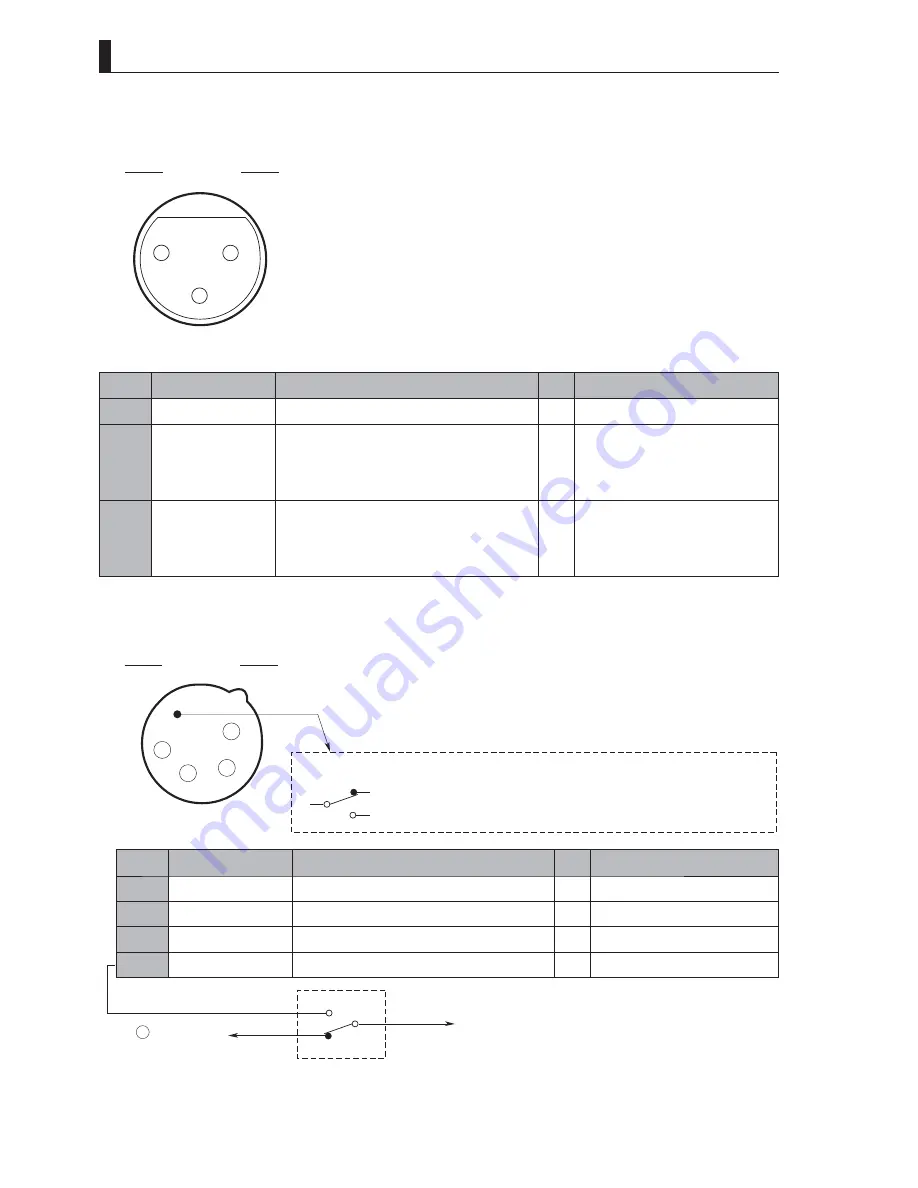
■
MIC-1 Connector and MIC-2 Connector
Used to connect for input to a microphone. (600
Ω
balanced input)
1
3
2
Insertion Side
Receptacle
Camera head side : HA16PRM-3SE (mounted on a board) (HRS)
Cable side
: XLR-3-12C (3-pin male plug) or equivalent
Pin No.
Name
Function
I/O
External Interface
①
MIC (SHIELD)
MIC input shield
―
②
MIC (HOT)
MIC (HOT) line
600
Ω
balanced input
When AB power is supplied
: DC 12V
When +48 phantom power is supplied : DC 48V
IN
③
MIC (COLD)
MIC (COLD) line
600
Ω
balanced input
When AB power is supplied
: DC 0V
When +48 phantom power is supplied : DC 48V
IN
■
DC-IN Connector
Used to connect external power supply.
This connector is built in an external switch.
NC (Normally closed
NO (Normally open
: By connecting the connector, the contact is opened.)
: By connecting the connector, the contact is closed.)
SW
COM
1
2
3
4
Insertion Side
Camera head side : HA16RX-4P (SW1)
Cable side
: XLR-4-11C (4-pin female plug) or equivalent
Receptacle
Pin No.
Name
Function
I/O
External Interface
①
+12 V RET
+12V input RET
IN
②
NC
―――――――――――――――――――――
―
③
NC
―――――――――――――――――――――
―
④
+12 V IN
+12V input (11V to 16V)
IN
COM
NO
NC
Pin A of connector on
VTR (DC +12V input)
To power switch
Summary of Contents for HDK-55
Page 1: ...HIGH DEFINITION CAMERA SYSTEM HDK 55 FA 55 OPERATION MANUAL...
Page 2: ......
Page 17: ...1 OUTLINE...
Page 18: ...2 HDK 55 1206 VER1 U...
Page 24: ...8 HDK 55 1206 VER1 U 1 2 Operating Systems...
Page 26: ......
Page 27: ...2 NAME and FUNCTION...
Page 28: ...12 HDK 55 1206 VER1 U...
Page 47: ...3 INSTALLATION and CONNECTION...
Page 48: ...32 HDK 55 1206 VER1 U...
Page 50: ...3 1 Preparation 34 HDK 55 1206 VER1 U...
Page 52: ......
Page 54: ......
Page 70: ...54 HDK 55 1206 VER1 U...
Page 71: ...4 OPERATION...
Page 72: ...56 HDK 55 1206 VER1 U...
Page 86: ...70 HDK 55 1206 VER1 U...
Page 87: ...5 CAMERA SETTINGS and ADJUSTMENT...
Page 88: ...72 HDK 55 1206 VER1 U...
Page 115: ...6 TROUBLE SHOOTING and MAINTENANCE...
Page 116: ...100 HDK 55 1206 VER1 U...
Page 126: ...110 HDK 55 1206 VER1 U...
Page 127: ...7 SPECIFICATIONS...
Page 128: ...112 HDK 55 1206 VER1 U...
Page 132: ...116 HDK 55 1206 VER1 U 7 2 External Dimensions Diagram Left View 94 3 7 1 337 5 270 5...
Page 134: ...118 HDK 55 1206 VER1 U 7 2 External Dimensions Diagram Rear View 138 5 3...
Page 150: ...134 HDK 55 1206 VER1 U...
Page 152: ......
Page 153: ......


