background image

 Glossary 

2014-04-15 

39


Term 

Explanation 

DVI 

Digital video standard, introduced by the Digital 
Display Working Group (

http://www.ddwg.org

). Single 

Link and Dual Link standard are distinguished. The 
signals have TMDS level. 

DVI-I 

A combined signal (digital and analog) that allows 
running a VGA monitor at a DVI-I port – in contrast to 
DVI-D (see DVI). 

EGA 

The Enhanced Graphics Adapter (EGA) is an old 
analog graphic standard, introduced by IBM in 1984. 
A D-Sub 9 connector is used for connection. 

Fiber 

Single-mode or multi-mode fiber cables 

HDMI 

An interface for an all-digital transmission of audio 
and video data. It is differentiated between the HDMI 
standards 1.0 to 1.4a. 
The signals have TMDS level. 

KVM 

Keyboard, video and mouse 

Mini-XLR 

Industrial standard for electrical plug connections  
(3 pole) for the transmission of digital audio and 
control signals 

Multi-mode 

62.5µ multi-mode fiber cable or 50µ multi-mode fiber 
cable 

OSD 

The On-Screen-Display is used to display information 
or to operate a device. 

Quad-Head 

A system with four video connections 

RCA (Cinch) 

A non-standard plug connection for transmission of 
electrical audio and video signals, especially with 
coaxial cables 

S/PDIF 

A digital audio interconnect that is used in consumer 
audio equipment over relatively short distances. 

SFP 

SFPs (Small Form Factor Pluggable) are pluggable 
interface modules for Gigabit connections. SFP 
modules are available for Cat X and fiber 
interconnect cables. 

Single Link  

A DVI-D interface for resolutions up to 1920x1200 by 
signal transmission of up to 165 MPixel/s (24-bit). 
Alternative frequencies are Full HD (1080p), 2K HD 
(2048x1080) and 2048x1152. 

Single-Head 

A system with one video connection 

Single-mode 

9µ single-mode fiber cable 

Summary of Contents for 485 Series

Page 1: ...IHSE GmbH Maybachstrasse 11 88094 Oberteuringen Germany info ihse de www ihse de Tel 49 7546 9248 0 Fax 49 7546 9248 48 User Manual Edition 2014 04 15 Draco Cross Repeater Model 485 Series ...

Page 2: ...this manual the manufacturer assumes no liability for errors or omissions The manufacturer assumes no liability for damages resulting from the use of the information contained herein The manufacturer reserves the right to change specifications functions or circuitry of the product without notice The manufacturer cannot accept liability for damage due to misuse of the product or due to any other ci...

Page 3: ... Device Views 11 3 6 1 2 fold Vario Chassis 474 BODY2 2R 11 3 6 2 2 fold Vario Chassis 474 BODY2N 12 3 6 3 4 fold Vario Chassis 474 BODY4 4R 13 3 6 4 6 fold Vario Chassis 474 BODY6R 14 3 6 5 6 fold Vario Chassis 474 BODY6BP 15 3 6 6 6 fold Vario Chassis 474 BODY6BPF 16 3 6 7 21 fold Vario Chassis 474 BODY21R 17 3 6 8 Model 485 BC 18 3 6 9 Model 485 BS 18 3 6 10 Model 485 BX 18 3 6 11 Model 485 BCC...

Page 4: ... 2 1 Cat X 27 7 2 2 Fiber 28 7 3 Connector Pinouts 29 7 4 Power Supply 30 7 5 Environmental Conditions 30 7 6 Size 31 7 7 Shipping Weight 32 8 Troubleshooting 33 8 1 General Failures 33 9 Technical Support 34 9 1 Support Checklist 34 9 2 Shipping Checklist 34 10 Certificates 35 10 1 CE Declaration Of Conformity 35 10 2 North American Regulatory Compliance 36 10 3 Product Safety 36 10 4 WEEE 37 10 ...

Page 5: ...s The following symbols are used in this manual This symbol indicates an important operating instruction that should be followed to avoid any potential damage to hardware or property loss of data or personal injury This symbol indicates important information to help you make the best use of this product This symbol indicates best practice information to show recommended and optimal ways to use thi...

Page 6: ...rs to be defective or has a damaged chassis Connect all power supplies to grounded outlets In each case ensure that the ground connection is maintained from the outlet socket through to the power supply s AC power input Do not connect the link interface to any other equipment particularly network or telecommunications equipment Take any required ESD precautions In order to disconnect the device co...

Page 7: ...between a KVM extender CON or CPU Unit or even a KVM matrix In addition to that the device can also be used for media conversion from Cat X to fiber or vice versa The device is available as a pure Cat X or fiber version repeater and as a hybrid version of Cat X and fiber cross repeater for an additional electrical optical signal conversion Pos 5 806 IHSE Beschreibung System Übersicht 485 xx 11 mod...

Page 8: ... a KVM matrix The Cross Repeater communicates with both the KVM extenders and a KVM Matrix via the interconnect cables 1 2 4 5 3 7 6 1 2 4 5 3 7 6 System Overview 1 Source computer CPU 2 KVM Extender CPU Unit 3 Interconnect cable Cat X or fiber 4 Cross Repeater 5 Interconnect cable Cat X or fiber 6 KVM Extender CON Unit 7 Console monitor keyboard mouse See Chapter 4 3 Page 23 for installation exam...

Page 9: ...al power supply unit 474 BODY4R Empty chassis for up to 4 boards 1x external power supply unit preparation for redundancy for a second power supply unit external 474 BODY6R Empty chassis for up to 6 boards 1x internal power supply unit preparation for redundancy for a second power supply unit external 474 BODY6BP Empty chassis for up to 6 boards active backplane 2x internal power supply unit redun...

Page 10: ...en 474 xx 6 mod_1304580008551_6 doc 50839 2 1 3 4 Accessories Upgrade Kits Model Description 474 2RMK 19 1U rack mount kit for 2 fold chassis 474 2NRMK 19 1U rack mount kit for 2 fold chassis with internal PSU 474 4RMK 19 1U rack mount kit for 4 fold chassis 474 6RMK 19 1U rack mount kit for 6 fold chassis 474 VPLATE Fastening strips for screw or snap on for 2 4 and 6 fold chassis 474 OPTRED Retro...

Page 11: ... supply unit 100 240 VAC 5 VDC 4 A 474 PSULOCK IEC connection cable for power supply lockable Pos 9 806 IHSE Beschreibung Geräteansichten UEB_Geräteansichten 5 mod_1278573737808_6 doc 41654 2 1 3 6 Device Views Pos 10 806 IHSE Beschreibung Geräteansichten 474 xx 2 fach Vario Gehäuse 474 BODY2 2R 6 mod_1304580280566_6 doc 50858 3 1 3 6 1 2 fold Vario Chassis 474 BODY2 2R CPU and CON Unit 1 2 3 4 Re...

Page 12: ... 4 Connect to 5VDC power supply redundancy The 2 fold vario chassis with an internal power supply is not equipped with a fuse on its primary side Therefore the protection against excessive currents has to be provided by the electrical installation of the building Pos 12 806 IHSE Beschreibung Geräteansichten 474 xx 4 fach Vario Gehäuse 474 BODY4 4R 6 mod_1304580359098_6 doc 50876 3 1 ...

Page 13: ... 4 Slot for modules 4 5 Slot for modules 2 6 Connect to 5VDC power supply redundancy optional For operation with three KVM Extender CON modules and a USB 2 0 CON module in a 4 fold vario chassis two power supplies are necessary In this case redundancy is inapplicable Pos 13 806 IHSE Beschreibung Geräteansichten 474 xx 6 fach Vario Gehäuse 474 BODY6R 6 mod_1304580442488_6 doc 50894 3 1 ...

Page 14: ...or modules 4 8 Slot for modules 2 For operation with KVM Extender modules in a 6 fold vario chassis two power supplies are necessary In this case redundancy is inapplicable The 6 fold vario chassis is not equipped with a fuse on its primary side Therefore the protection against excessive currents has to be provided by the electrical installation of the building Pos 14 806 IHSE Beschreibung Gerätea...

Page 15: ... 1 2 Connect to power supply 2 redundancy 3 Grounding 3 4 5 1 2 6 Rear View 1 Slot for modules 5 2 Slot for modules 3 3 Slot for modules 1 4 Slot for modules 6 5 Slot for modules 4 6 Slot for modules 2 Pos 15 806 IHSE Beschreibung Geräteansichten 474 xx 6 fach Vario Gehäuse 474 BODY6BPF 11 mod_1392644763729_6 doc 132650 3 1 ...

Page 16: ... 3 6 7 1 2 8 4 5 Rear View 1 Slot for modules 5 2 Slot for modules 3 3 Slot for modules 1 4 Connect to power supply 1 5 Connect to power supply 2 redundancy 6 Slot for modules 2 7 Slot for modules 4 8 Slot for modules 6 Pos 16 806 IHSE zz_Layout Seitenumbruch 8 mod_1348581820516_0 doc 69462 1 ...

Page 17: ... 1 3 6 7 21 fold Vario Chassis 474 BODY21R CPU and CON Unit 1 Rear View 1 Slots for modules 1 21 1 2 3 4 Front View 1 Connect to power supply 2 2 Locking for power supply 2 redundancy 3 Locking for power supply 1 standard 4 Connect to power supply 1 Pos 18 806 IHSE Beschreibung Geräteansichten 485 xx 485 BC 11 mod_1395150015320_6 doc 140874 3 1 ...

Page 18: ...05 3 1 3 6 9 Model 485 BS Module 1 2 3 Rear View 1 Service port 2 Connect to interconnect cable 1 3 Connect to interconnect cable 2 Pos 20 806 IHSE Beschreibung Geräteansichten 485 xx 485 BX 11 mod_1395153879791_6 doc 140936 3 1 3 6 10 Model 485 BX Module 1 2 3 Rear View 1 Service port 2 Connect to interconnect cable 1 3 Connect to interconnect cable 2 Pos 21 806 IHSE Beschreibung Geräteansichten ...

Page 19: ...le 2 repeater 2 Pos 22 806 IHSE Beschreibung Geräteansichten 485 xx 485 BSS 11 mod_1395154011282_6 doc 140998 3 1 3 6 12 Model 485 BSS Module 2 3 5 6 1 4 Rear View 1 Service port repeater 1 2 Connect to interconnect cable 1 repeater 1 3 Connect to interconnect cable 2 repeater 1 4 Service port repeater 2 5 Connect to interconnect cable 1 repeater 2 6 Connect to interconnect cable 2 repeater 2 Pos ...

Page 20: ...ter 1 2 Connect to interconnect cable 1 repeater 1 3 Connect to interconnect cable 2 repeater 1 4 Service port repeater 2 5 Connect to interconnect cable 1 repeater 2 6 Connect to interconnect cable 2 repeater 2 Pos 24 806 IHSE Beschreibung Diagnose LEDs UEB_Diagnose_LEDs 6 mod_1304584004723_6 doc 51146 1 ...

Page 21: ... Pos LED Status Description Off Connection available 1 4 Failure LED green On or Flashing Connection failure flashing for about 20 s following a connection failure Flashing No connection via interconnect cable 2 5 Status LED green On Connection available LED 3 Device Status LED color Description Red Device ready Blue Link 1 left connector available Link 2 right connector not detected Green Link 2 ...

Page 22: ...c 141123 23 1 4 2 System anschließen First time users are recommended to setup the system in the same room as a test setup This will allow you to identify and solve any cabling problems and experiment with your system more conveniently Please verify that interconnect cables interfaces and handling of the devices comply with the requirements see Chapter 7 Page 26 4 2 1 Cross Repeater Setup 1 Switch...

Page 23: ...e Media Conversion 1 Source computer CPU 2 KVM Extender CPU Unit 3 Interconnect cable Cat X 4 Cross Repeater 5 Interconnect cable fiber 6 KVM Extender CON Unit 7 Console monitor keyboard mouse The example shown in this application scenario will be primarily recommended if connections through KVM matrix must be bypassed in case of major matrix problems Therefore KVM extenders with Cat X and with fi...

Page 24: ... Dual Media Conversion 1 Source computer CPU 2 KVM Extender CPU Unit 3 Interconnect cable Cat X 4 Cross Repeater 1 5 Interconnect cable fiber 6 Cross Repeater 2 7 Interconnect cable Cat X 8 KVM Extender CON Unit 9 Console monitor keyboard mouse Pos 30 806 IHSE Konfiguration UEB_Konfiguration 5 mod_1278575517073_6 doc 41846 1 1 ...

Page 25: ... and is ready for use per default Pos 32 806 IHSE Betrieb UEB_Betrieb 5 mod_1278577614980_6 doc 41970 1 1 6 Operation Pos 33 806 IHSE Betrieb 485_Einleitung 11 mod_1395156725331_6 doc 141216 1 The Cross Repeater does not have any adjustable operating modes and is ready for use per default Pos 34 806 IHSE Technische Daten UEB_Technische Daten 5 mod_1278578165261_6 doc 42096 1 1 ...

Page 26: ... at both ends All four cable wire pairs are used Pos 37 806 IHSE Technische Daten Schnittstellen Glasfaser SFP Typ LC 5 mod_1278937700855_6 doc 43149 3 1 7 1 2 Fiber SFP Type LC Interconnect Communication of fiber devices is performed via Gigabit SFPs that are connected to suitable fibers fitted with connectors type LC see Chapter 7 2 2 Page 28 The correct function of the device can only be guaran...

Page 27: ... of Interconnect Cable The Cross Repeater requires interconnect cabling specified for Gigabit Ethernet 1000BASE T The use of solid core AWG24 shielded Cat 5e or better is recommended Cat X Solid Core Cable AWG24 S UTP Cat 5e cable according to EIA TIA 568 B Four pairs of wires AWG24 Connection according to EIA TIA 568 B 1000BASE T Cat X Patch Cable AWG26 8 S UTP Cat 5e cable according to EIA TIA 5...

Page 28: ...tch cable I AD ZN H 4G50 in house or outdoor breakout cable resistant Multi mode 62 5μm Two fibers 62 5μm I V ZN HH 2G62 5 in house breakout cable A DQ ZN B2Y 4G62 5 outdoor cable with protection against rodents Maximum Acceptable Cable Length Type of cable Maximum Acceptable Cable Length Single mode 9μm 10 000 m 32 800 ft Multi mode 50μm OM3 1 000 m 3 280 ft Multi mode 50μm 400 m 1 300 ft Multi m...

Page 29: ... 4 n c 5 1 5 GND Black Pos 45 806 IHSE Technische Daten Pinbelegungen RJ45 5 mod_1278578820011_6 doc 42405 1 RJ45 Picture Pin Signal Pin Signal 1 D1 5 D3 2 D1 6 D2 3 D2 7 D4 8 1 4 D3 8 D4 Pos 46 806 IHSE Technische Daten Pinbelegungen Glasfaser SFP Typ LC 5 mod_1278938501151_6 doc 43210 1 Fiber SFP Typ LC Picture Diode Signal 1 Data OUT 1 2 2 Data IN Pos 47 806 IHSE Technische Daten Stromversorgun...

Page 30: ...Current Max Voltage 474 BODY2 2R 3 000 mA 5 VDC 474 BODY2N 5 000 mA 5 VDC 474 BODY4 4R 5 000 mA 5 VDC 474 BODY6R 8 000 mA 5 VDC Power Requirement Power Requirement per Unit Cross Repeater Max 300 mA Pos 48 806 IHSE Technische Daten Einsatzbedingungen ATB_Einsatzbedingungen 5 mod_1278578980026_6 doc 42480 2 1 7 5 Environmental Conditions Operating Temperature 41 to 113 F 5 to 45 C Storage Temperatu...

Page 31: ...x 41 mm 11 5 x 5 8 x 1 7 Shipping Box 550 x 365 x 115 mm 21 7 x 14 4 x 4 5 Devices in the 6 fold Vario Chassis 6R CPU Unit CON Unit 442 x 147 x 41 mm 17 4 x 5 8 x 1 7 Shipping Box 760 x 365 x 115 mm 29 9 x 14 4 x 4 5 Devices in the 6 fold Vario Chassis 6BP 6BPF CPU Unit CON Unit 442 x 250 x 41 mm 17 4 x 9 8 x 1 7 Shipping Box 550 x 372 x 155 mm 21 7 x 14 6 x 6 1 Devices in the 21 fold Vario Chassi...

Page 32: ...pping Box 2 6 kg 5 7 lb Devices in the 4 fold Vario Chassis CPU Unit CON Unit 0 9 kg 2 0 lb Shipping Box 3 4 kg 7 5 lb Devices in the 6 fold Vario Chassis 6R CPU Unit CON Unit 1 4 kg 3 1 lb Shipping Box 4 6 kg 10 1 lb Devices in the 6 fold Vario Chassis 6BP 6BPF CPU Unit CON Unit 2 5 kg 5 5 lb Shipping Box 3 5 kg 7 7 lb Devices in the 21 fold Vario Chassis CPU Unit CON Unit 10 0 kg 22 1 lb Shippin...

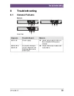
Page 33: ... 3 4 5 1 2 3 4 5 Rear View Diagnosis Possible Reason Measure LED 3 off Power supply Check power supply units and the connection to the power network LED 2 off or LED 5 off Connection between Cross Repeater and KVM extender unit or KVM matrix Check interconnect cables and connections Pos 54 806 IHSE Technische Unterstützung ATB_Technische Unterstützung 5 mod_1278579487089_6 doc 42650 122 1 ...

Page 34: ...the existing manual Nature circumstances and duration of the problem Components included in the system such as graphic source CPU OS graphic card monitor USB HID USB 2 0 devices interconnect cable including manufacturer and model number Results from any testing you have done 9 2 Shipping Checklist 1 To return your device contact your dealer to obtain a RMA number Return Material Authorization 2 Pa...

Page 35: ...ized standards for Information Technology Equipment EN 55022 2010 A1 2007 Class A EN 55024 2010 A1 2001 A2 2003 This declaration certifies the conformity to the specified directives but contains no assurance of properties The safety instructions and installation guidelines noted in this manual shall be considered in detail Compliance with the specifications for cable lengths and types is mandatory...

Page 36: ...rect the interference at his own expense Changes or modifications not expressly approved by the party responsible for compliance could void the user s authority to operate the equipment Shielded cables must be used with this equipment to maintain compliance with radio frequency energy emission regulations and ensure a suitably high level of immunity to electromagnetic disturbances All power suppli...

Page 37: ...HSE Zertifikate ATB_RoHS 5 mod_1278579714214_6 doc 42722 2 1 10 5 RoHS RoHS 2 This device complies with the Directive 2011 65 EU of the European Parliament and of the council of 8 June 2011 on the restriction of the use of certain hazardous substances in electrical and electronic equipment RoHS 2 RoHS II The device labels carry a respective marking Pos 60 806 IHSE Glossar ATB_Glossar 5 mod_1278576...

Page 38: ...d CVBS and it is part of the PAL TV standard CON Unit Component of a KVM Extender or Media Extender to connect to the console monitor s keyboard and mouse optionally also with USB 2 0 devices Console Keyboard mouse and monitor CPU Unit Component of a KVM Extender or Media Extender to connect to a source computer CPU CVBS The analog color video baseband signal CVBS is also called Composite Video an...

Page 39: ...trical plug connections 3 pole for the transmission of digital audio and control signals Multi mode 62 5µ multi mode fiber cable or 50µ multi mode fiber cable OSD The On Screen Display is used to display information or to operate a device Quad Head A system with four video connections RCA Cinch A non standard plug connection for transmission of electrical audio and video signals especially with co...

Page 40: ...e video connections USB HID USB HID devices Human Interface Device allow for data input There is no need for a special driver during installation New USB HID device found is reported Typical HID devices include keyboards mice graphics tablets and touch screens Storage video and audio devices are not HID VGA Video Graphics Array VGA is a computer graphics standard with a typical resolution of 640x4...

Reviews: