background image

M                                         

DSP


DIGITAL


POWER AMPLIFIER 


Page 

7

  / 

37

Screensaver 2


Chapter 4: Software Introduction 

 
Mconsole is a software for users to quickly interact with the parameters of one or more machines. It can store the 
configuration parameters of the device in a disk file to configure and parameter preset scenes for multiple machines or 
different places of use. This provides users with its convenient switching and restoring. This product has high execution 
efficiency and clear interface structure. The UI of this product adopts a self-developed control library, and can be 
customized and modified according to the needs of customers, which enhances the user experience. 
 

Chapter 5: Software Installation 


5.1 Operating environment 

The software is suitable for WIN7/WIN8/WIN10 x86/x64 operating system with Microsoft .NET Framework 4.0 runtime.   


5.2 Software installation 
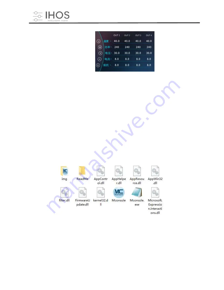
This software is a green version, the green version of the software does not need to install the main program, the folder 
contains the following files or folders, all of which are indispensable. The green version of the software does not include 
the Microsoft .NET Framework 4.0 runtime. If necessary, please download and install it from the official Microsoft website. 
 

Summary of Contents for Quadro DSP 6.4 1500W Series

Page 1: ...M DSP DIGITAL POWER AMPLIFIER Quadro DSP 6 4 User Manual...

Page 2: ...control button 16 6 9 Function module interface 16 6 10 List of input and output channels 17 Chapter 7 Introduce of function interface 17 7 1 Interface of input channel module 17 7 2 Test signal funct...

Page 3: ...um Hotel Meeting Room Shopping Mall Retail Store Restaurant Chapter 2 Technical Parameters 2 1 Features Network TCP IP control and manage multiple devices Remote on off amplifier 4 3 IPS colorful capa...

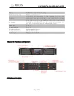
Page 4: ...01W 1000W Release time 1 2895ms Output Volume Mute Phase Level detector DSP Preset 80 packages Control Mode Ethernet USB RS485 RS232 Network Model TCP IP 1000base T 100base TX RJ45 Channels 4 Minimum...

Page 5: ...rt circuit back electromotive force peak current limiter surge current limiter start delay power breaker protection power supply overvoltage undervoltage protection PC Software Mconsole for controllin...

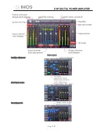
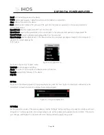
Page 6: ...M DSP DIGITAL POWER AMPLIFIER Page 5 37 Home screen Sensitive adjustment Select input source Operating mode...

Page 7: ...M DSP DIGITAL POWER AMPLIFIER Page 6 37 Support channels link Preset interface Control and Dante IP setting Select screen saver mode freely Screensaver 1...

Page 8: ...adopts a self developed control library and can be customized and modified according to the needs of customers which enhances the user experience Chapter 5 Software Installation 5 1 Operating environ...

Page 9: ...able file in the folder to enter the software theme interface as shown in Figure 5 1 Precautions Some connection methods do not support multiple host computers to be turned on at the same time Please...

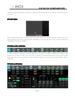
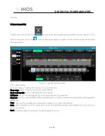
Page 10: ...ellow corresponding position as follows 1 Menu bar 2 Scan button 3 Setting button 4 Link button 5 Device list 6 Module button 7 Homepage monitor area 8 Module function interface 9 List of input and ou...

Page 11: ...tched to the selected state after the hard switch is turned on 4 Click the button in the frame to quickly switch the routing status There are 4 options available stereo parallel bridge and matrix 6 1...

Page 12: ...y enter the exact value in the input box is the mute button 2 When the input is overloaded the indicator light will light up as follows 3 You can quickly set the gain mute and phase 4 Multiple input s...

Page 13: ...equipment will not affect the existing equipment Open open an existing device management project from the computer disk Save save the current device management project in the computer disk Save as sav...

Page 14: ...the device parameters Disconnect disconnect the connected device Connect all devices connect and download the device parameters of all devices in the device list Disconnect all devices disconnect all...

Page 15: ...kage and export to the computer to generate the preset package file 6 2 5 System Figure 6 2 5 System menu As shown in Figure 6 2 5 System menu Language multi language switching About the current host...

Page 16: ...eds to be set at the same time in the left frame move to the link group in the middle frame and then select the grouping setting parameters on the right finally press the OK button to make the groupin...

Page 17: ...ter system and display it in the lower left corner of the software to facilitate the management of the device IP address 6 8 Function module control button In order to facilitate the interaction of di...

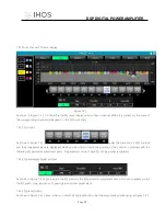
Page 18: ...functions 6 10 List of input and output channels It can display the level gain input mode channel name and other information of each channel control the corresponding channel gain DSP function master...

Page 19: ...t source sensitivity in the corresponding input channel In the sensitivity setting you can choose between 0dBu and 6dBu two gears 7 2 Test signal function Select sine wave pink noise white noise in th...

Page 20: ...utton the figure 7 2 below input channel noise gate setting module pops up Figure 7 2 input noise gate setting module As shown in Figure 7 2 above click the noise gate switch in the upper right corner...

Page 21: ...re Phase curve display the phase curve of the current channel Show control points show or hide all balance control points Full bypass turn on or off all equalizer EQ of the current channel at the same...

Page 22: ...detailed values are displayed which can be used to locate the position of the controls Combined with the following EQ parameter adjustment items the parameter value of each EQ can be precisely adjuste...

Page 23: ...t to realize the archive call delete and rename functions of the equalizer setting parameters 7 5 Matrix mix Double click in the module button the following Figure 7 5 matrix mixing setting module wil...

Page 24: ...atrix block Click the reset button to reset the matrix mixing function to the initial one to one state click the clear button to clear all the matrix mixing functions and there is no correspondence be...

Page 25: ...e reset button on the far right can directly reset the default value of the channel delay Note ft inches cm centimeters ms milliseconds 7 8 Output compressor Double click in the module button the foll...

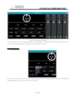
Page 26: ...AL POWER AMPLIFIER Page 25 Figure 7 7 Output limiter setting module 7 10 Output module Double click in the module button and the output setting module shown in Figure 7 8 pops up Figure 7 8 Output set...

Page 27: ...ion 2 The channel name input mode and channel grouping can only be viewed and there is no editing function 3 In the channel gain function you can see the level status of the input channel signa l 4 Am...

Page 28: ...t and output channels homepage the right part is the output channel as shown in Figure 7 10 Figure 7 10 Output channel The content from top to bottom in the output channel interface includes channel n...

Page 29: ...e 7 10 channels link interface will pop up Figure 7 10 Channels link interface As shown in the figure above the three lists from left to right are divided into channel list group list and parameter li...

Page 30: ...and remove device button The mute button can directly control the mute of all input and output channels of the entire device The status button can refresh the status of the device instantly If the de...

Page 31: ...ation display the current device name device grouping and factory name information If the factory name is to be displayed you need to press the hidden shortcut key CTRL ALT F12 where device name and f...

Page 32: ...corresponding channel click the OK button to save and update the name of the channel immediately Note that the length of the channel name is limited to 5 English letters and numbers 7 18 Channels cop...

Page 33: ...ten and the device parameters after recall All of them will be restored to the factory default parameters other gears can be freely saved recalled deleted and other operations The function buttons on...

Page 34: ...are upgrade interface as shown in the figure above After selecting the corresponding upgrade file in the Upgrade File column click Start Upgrade in the upper right corner and the system will automatic...

Page 35: ...th methods need to via a switch or router in wired connection 2 Either which connection method is chosen it is necessary to configure the routing through the official Dante Controller computer softwar...

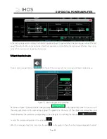
Page 36: ...troduction Double click FIR module button enter into FIR function interface click Design to enter into design interface There are 5 area in FIR interface Setting IMPORT Import FIR preset files to the...

Page 37: ...terface show with amplitude curve Phase Interface show with phase curve 72dB Show content within 72dB of amplitude accuracy 144dB Show content within 144dB of amplitude accuracy Curve 108 36 Amplitude...

Reviews: