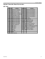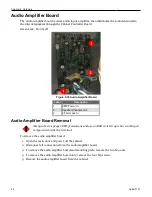
Chapter 2 Hardware
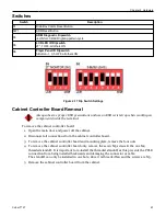
Switches
Switch
Description
S1
Brain Box Comm Reset Button
SW1
ARM Reset Button
S3
ARM Diagnostic Dipswitch
-4 ON for LCD LED lighting pattern cycle
S5
LCD LED ID Dipswitch
27" -1 OFF, all others ON
S6
Player Panel ID Dipswitch
5-Button - 1, 3, 5 OFF, all others ON
Figure 2-17 Dip Switch Settings
Cabinet Controller Board Removal
Always observe proper ESD precautions and use an ESD wrist strap when working on
components inside the terminal.
To remove the cabinet controller board:
1. Open the main door and power off the cabinet.
2. Disconnect all connections from the cabinet controller board.
3. To remove the cabinet controller board and mounting plate, remove the four nuts.
4. To remove the cabinet controller board only, remove the seven M3 screws & the one M4
threaded standoff. It is important to re-install the threaded standoff, as this prevents the PCI-E
connection from being installed backwards and damaging the connector or cable.
The standoff can only be installed in one hole, since it is threaded M4 and the screws are M3.
5. Remove the cabinet controller board from the cabinet.
Cobalt™ 27
43
Summary of Contents for Cobalt 27
Page 5: ...CFInit 85 Appendix A Stand Mounting 87 Cobalt 27 5...
Page 6: ...6 Cobalt 27...
Page 12: ...Chapter 1 Cobalt Overview Dimensions Figure 1 2 Dimensions 12 Cobalt 27...
Page 26: ...26 Cobalt 27 Chapter 1 Cobalt Overview...
Page 40: ...Chapter 2 Hardware Figure 2 16 Cabinet Controller Board Connectors 40 Cobalt 27...
Page 76: ...76 Cobalt 27 Chapter 2 Hardware...
Page 88: ...Appendix A Stand Mounting Figure A 2 Stand Drill Pattern 88 Cobalt 27...


