background image

Quick Start 
Guide


– 
6  –


5. 

Verify AP Operation   

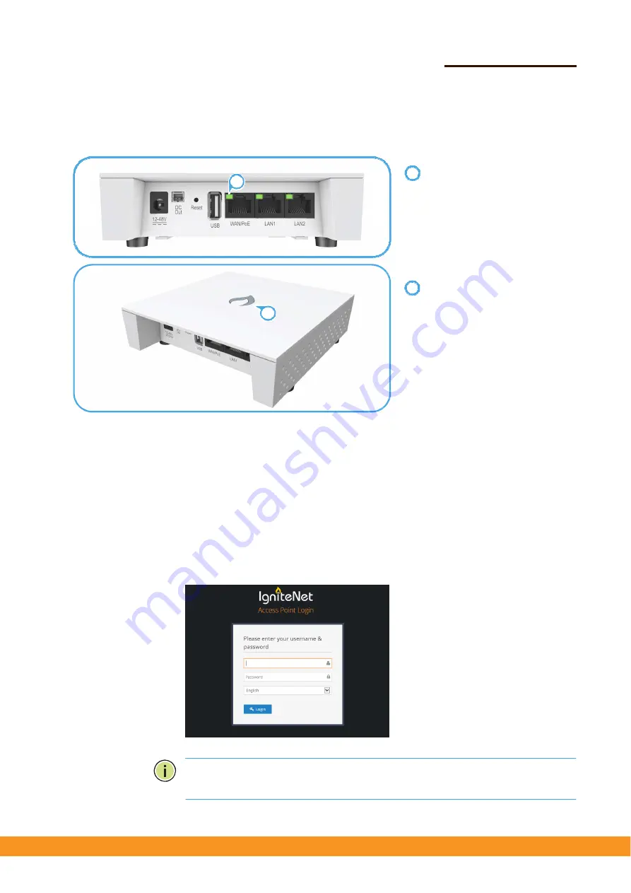
Verify basic AP operation by checking the system LEDs. 


The 

WAN/PoE 

port link/activity LED 

should be on/blinking green. 
When connected, the 

LAN1 

and 

LAN2 

port link/activity LEDs 

should also be on/blinking green. 


The system/wireless LED should be 
on red when the AP is powered on, 
or on/blinking green (2.4 GHz) or 
blue (5 GHz). 


6. 

Connect to the Web


User Interface


When  managed in  a  stand-alone mode, the  AP  offers  a  web-based management 
interface for the configuration of all the unit’s features. If cloud-managing the AP, 
go directly to 

“Manage the AP with the IgniteNet Cloud Controller” on page 7


To access the web interface, connect a PC directly to the AP’s 

LAN1 

or 

LAN2 

RJ-45 

port. You must first set your PC IP address to be on the same subnet as the AP (that 
is, the PC and AP addresses must both start 192.168.2.x with a subnet mask of 
255.255.255.0). In a web browser, enter the AP’s default management IP address of 
192.168.2.1 to access the web login page. 


Log in to the web interface using  the 
default settings: 


Login Name — root 


Password — admin123 


Note: 

To reset the AP to factory default settings, press and hold down the AP’s 

Reset 

button for 5 seconds. 


1

2

Summary of Contents for Spark IR-AC750

Page 1: ...r by the universal power supply included in the package through an Ethernet cable connection from a Power over Ethernet PoE injector or from a 802 3af compliant PoE switch The Cloud Enabled Enterprise...

Page 2: ...fessional contractor knowledgeable in local radio regulations prior to equipment installation 1 Unpack the AP Unpack the AP and check the package contents Cloud Enabled Enterprise Access Point Spark A...

Page 3: ...r the wall plugs and screws Drill four holes for the wall plugs and then insert the plugs and tap them flush with the wall surface Align the mounting plate with the four holes and then use the four sc...

Page 4: ...t sizes of suspended ceiling T bars The position illustrated below is for 15 mm bars Use the position at a 90 degrees angle for 24 5 mm bars Suspended Ceiling Mounting Press the retention clips of the...

Page 5: ...the AC DC power adapter provided in the package by a PoE power injector Spark AC750 Powering the AP with the AC DC Power Adapter Connect the cable from the power adapter to the DC power jack on the AP...

Page 6: ...on of all the unit s features If cloud managing the AP go directly to Manage the AP with the IgniteNet Cloud Controller on page 7 Toaccess the web interface connect a PC directly to the AP s LAN1 or L...

Page 7: ...t Cloud Controller Go to cloud ignitenet com to register your AP Log in and select Devices from the menu Click Add Device and enter the AP serial number and MAC address to register the AP with your cl...

Page 8: ...ac Radio Frequencies 2412 2462 MHz 5180 5240 MHz 5745 5825 MHz Power Supply AC Power Adapter Input 100 240 VAC 50 60 Hz auto sensing Output 12 24 VDC 1 5 A maximum 12 VDC Passive PoE Input Power 24 V...

Page 9: ...ns may cause harmful interference to radio communications However there is no guarantee that interference will not occur in a particular installation If this equipment does cause harmful interference...

Page 10: ...ted rule knowledge The general user shall not attempt to install or change the setting 2 Installation location The product shall be installed at a location where the radiating antenna can be kept 20cm...

Reviews: