


MRBP.425241.001 UM version 1.1 01.05.2022 FD 329/330-3-
1 «Vega»
14
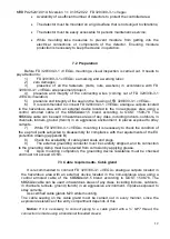
3. The information network organization must be carried out in a way that the voltage drop
on the
–24 V wire between the central processor and the detector does not exceed 8
V.
4. It is recommended to connect the detectors in a branch line from the main interface line.
Branches should be formed by installing repeater-splitters with galvanic isolation of the
type at the nodal points of the line. Each branch must serve a separate tank. Extension
of the main line beyond 1200 m must be carried out by inserting an interface repeater into
the line.
5. It is advisable to power the FD 329/330-3-
1 «VEGA» according to the beam scheme -
each tank has its own cable.
Allowable line length is determined by the formula:
L(km) = 25
ΔU(V) S (mm2) / Imax(mA),
where
ΔU(V) – allowable line voltage drop;
Imax(mA)
– max current consumption;
(Imax(mA)FD 329/330-3-
1 «VEGA» = 150 mA N(pcs.)
Notice: FD 329/330-3-
1 «VEGA» digital output protocol parameters are shown in Appendix
A.
5.1 Connection diagrams
Figure 4
– Connection diagram for an explosion-proof detector EEx


