


MRBP.425241.001 UM version 1.1 01.05.2022 FD 329/330-3-
1 «Vega»
13
8. Detector connection
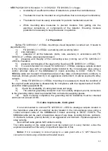
8.1 Power source requirements
Before connection it is necessary to:
- Calculate the total power consumption rate of the gas detection system in watts,
taking into account cold start.
- Select a power source with the appropriate power for the calculated load.
- Make sure the selected power source provides a regulated 24 VDC output voltage
for the entire system, taking into account allowable ripples. It is recommended to use
of a battery backup power supply to improve system reliability.
Notice: If it is required to be able to turn off the power supply, then a separate method
of turning it off must be provided.
8.2 Detector connection
To connect the detector:
-
fix the mounting bracket at the FD 329/330-3-
1 «VEGA» workplace, install a base on
it and fix it with a screw and a lock nut. The detector with a mounting bracket and its overall
dimensions are shown in figure 2;
- separate the base with cable gland from the detector housing;
-
install the connecting cable in the cable gland
и соединить проводники с
соответствующими клеммами,and connect the conductors to the corresponding terminals
located on the backplane:
Figures 4 and 5 show examples of connecting the detector to fire alarm control panels;
Figures 6 and 7 show diagrams of connecting the detector to fire alarm control panels
in the analogue signal using and digital output using mode;
Figures 8 and 9 show diagrams of connecting two detectors to fire alarm control system
via RS-485 interface with and w/o terminal box;
-
install the FD 329/330-3-
1 «VEGA» housing on the base and tighten the 3 screws;
-
turn the detector for correct targeting;
-
after applying power to the detector, it is necessary to control the internal IR and UV
radiation test sources, powered by a pulsed voltage. This radiation falls on the optical
sensitive elements of the IR channels (IR channel test lamp blinking at a frequency of 4-5
hertz for 1.5-2 seconds) and the UV channel (UV channel test lamp lighting once for 0.5
seconds), which allows the FD 329/330-3-1
«VEGA» to carry out a self-test every 30 minutes.
After successful passing of the test, at the FD 329/330-3-
1 «VEGA» output a «slow»
alternate red LEDs blinking appears in the window of the FD 329/330-3-1 FD 329/330-3-1
«VEGA» IR channel, which corresponds to the detector entering «Standard» mode.
Detector connection to RS-485 digital channel
1. It is recommended to connect the detectors to the bus via a terminal box. Detectors
connection to a terminal box is carried out by a cable with a recommended length of
not more than 0,5m. Cable must meet the cable gland requirements on the FD
329/330-3-
1 «VEGA» housing and terminal box. For the connection from terminal box
to the bus an armored cable with pairs of shielded twisted pairs can be used.
2. For the correct power supply network organization note that the supply voltage at the
terminals of the devices must be not less than 18 V and not more than 32 V, taking
into account the FD 329/330-3-
1 «VEGA» consumption.


