-6-
www.igmtools.com
MULTIPLE HAND HELD REMOTE SETUP
You can pair up to five (MAX) hand held remotes; however each hand
held remote needs to be setup individually following the programming
steps above.
If you setup a sixth hand held remote, it will override the first hand held
remote. If a seventh hand held remote is setup, it will override the second
hand held remote. And so on.
5. Assembly
5.1 Unpacking
Your 3HP Mobile Dust Cyclone comes packed in a single box. Before
attempting to assemble this machine, follow these directions for
unpacking:
1. Carefully cut the banding straps and remove them from the box.
2. Cut along the tape line at the top of the box.
3. Remove all parts from the top of the styrofoam and set aside.
4. Remove the styrofoam packing material from the top of the machine.
5. Carefully take out the machine components from the box and set aside.
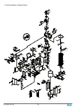
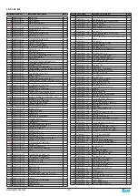
6. Using the diagram below, ensure that all parts are present and in good
condition.
Description
A. Motor
B. Remote cont Manual
C. Dust chute
D. Canister shield (front and back)
E. Top upright supports (3)
F. Canister cover plate
G. Drum insert (4)
H. HEPA Canister filter
I. Filter rotation shaft
J. Filter cleaning arm(2)
K. Crossbar
L. Collection bag for drum(3)
M. Cyclone funnel
N. Cyclone barrel
O. Intake cylinder
P. Octagon drum (front and back panel)
Q. Drum lid
R. Foot peddle bar
S. Filter end cap with 4” suction port
T. Octagon drum base panel
U. Lower upright supports (3)
V. Drum side plate (left and right)
W. Upright support reinforcement plate (3)
X. Foot peddle bar (left and right)
Y. Foot peddle assembly fittings
Y1. Lower triangular support plate (2)
Y2. Foot peddle bar support (2)
Y3. Lower support plate (2)
Z. Intake Reducer (8” by 6”) PFLUX2 only
AB. Intake adapter (8” by 4” x 3 ports) PFLUX3 only
AC. Autoclean plate
AD. Hardware box
Report any missing or damaged parts to your dealer or distributor. Prior to
tool assembly and use, read this manual thoroughly to familiarize yourself
with proper assembly, maintenance and safety procedures.
5.2 General Tool Assembly
This step requires two adults.
This 3HP Mobile Dust Cyclone is heavy,
be careful when lifting and handling it! Failure to comply may cause
serious injury and/or damage to the machine and/or property!
Tools Required
10 mm wrench / 12 mm wrench / 14 mm wrench
Phillips screwdriver. 4 mm hex wrench / 5 mm hex wrench
To assemble your dust cyclone, follow these steps:
For your own safety, do not connect the machine to the power source until
the machine is completely assembled. Please also make sure that you
read and understand the entire instruction manual.
ASSEMBLY TIME ESTIMATE 5-6 hours
Step 1: Remove the base which has been bolted to the (3) top upright
supports. Keep the (6) 3/8”x3/4” hex bolts and (6) 3/8” flat washers for
assembling the lower supports to the base. Keep the upper assembly
lifted for step 5.
Step 2: Turn base upside-down. Use (16) 5/16” x 3/4” hex bolts and (16)
5/16” flat washers. Attach the (2) 4” casters with brakes to the base. The
casters wit brakes should be attached to the side with the opening. The
remaining (2) 4” swivel casters must attach to the other end on the base.
Step 3: Turn the base over with it standing on the (4) 4” casters and
secure the three lower upright support panels using (6) 3/8” x 3/4” hex
bolts and (6) 3/8” x 7/8” flat washers..
A – shown with one dot is located on the canister side.
B – shown with two dots is located on the front side
C – shown with three dots is located on the opposite end.
Step 4. With the help of another person carefully lift the upper cyclone
assembly high enough to place on stands that you have completed in
steps 2 and 3. Take note on precisely positioning the upper cyclone
assembly onto the three lower upright supports. Using (6) 5/16” x 3/4” hex
bolts and (6) 5/16” flat washers connect and secure the upper and lower
upright supports.


