-5-
www.igmtools.com
Disconnecting power supply.
Turn the switch off, disconnect the
dust collector from the power supply, and allow the impeller to come to
a complete stop before leaving the machine unattended or doing any
service, cleaning, maintenance, or adjustments.
Suspended dust particles and ignition sources.
Do not operate the
dust collector in areas were explosion risks are high. Areas of high risk
include, but are not limited to, areas near pilot lights, open flames, or other
ignition sources.
Fire suppression.
Only operate the dust collector in locations that contain
a fire suppression system or have a fire extinguisher nearby.
Impeller hazards.
Do not place your hands or tools near the open inlet
during operation for any reason. The powerful suction could easily cause
accidental contact with the impeller, which will cause serious personal
injury or damage to the machine. Always keep small animals and children
away from open dust collection inlets.
Avoiding sparks.
Do not allow steel or rocks to strike the impeller—this
may produce sparks. Sparks can smolder in wood dust for a long time
before a fire is detected. If you accidentally cut Into wood containing tramp
metal (nails, staples, spikes, etc.), immediately turn off the dust collector,
disconnect it from power, and wait for the impeller to stop—then empty the
collection container into an approved airtight metal container.
Operating location.
To reduce respiratory exposure to fine dust, locate
permanently installed dust collectors away from the working area, or in
another room that is equipped with a smoke detector. Do not operate the
dust collector in rainy or wet locations—exposure to water may create a
shock hazard or decrease the life of the machine.
Static electricity.
Plastic dust lines generate high amounts of static
electricity as dust chips pass through them. Although rare, sparks caused
by static electricity can cause explosions or fire. To reduce this risk, make
sure all dust lines are thoroughly grounded by using a grounding wire.
Regular cleaning.
Regularly check/empty the collection bags or drum to
avoid the buildup of fine dust that can increase the risk of fire. Make sure
to regularly clean the surrounding area where the machine is operated—
excessive dust buildup on overhead lights, heaters, electrical panels, or
other heat sources will increase the risk of fire.
Warning: If precautions are not heeded, it may result in minor injury and/or
possible machine damage.
Warning: If precautions are not heeded, it may result in serious injury or
possibly even death.
SAVE THESE INSTRUCTIONS.
Refer to them often and use them to instruct others.
3.4
Motor Specifications
Your machine is wired for 400 volts, 50 HZ alternating current. Before
connecting the machine to the power source, make sure the switch is in
the “OFF” position.
3.5 Grounding Instructions
DANGER: THIS MACHINE MUST BE GROUNDED WHILE IN USE TO
PROTECT THE OPERATOR FROM ELECTRIC SHOCK.
1. This appliance must be connected to a grounded metal, permanent
wiring system; or an equipment-grounding conductor must be run with the
circuit conductors and connected to the equipment-grounding terminal or
lead on the appliance.
The installer, such as a qualified electrician, cut (or bend over) and
insulate the grounding conductor from a field wiring supply cable.
In the event of certain types of malfunctions or breakdowns, grounding
provides a path of least resistance for electric current—in order to reduce
the risk of electric shock.
Improper connection of the equipment-grounding wire can result in a
risk of electric shock. The wire with green insulation (with or without
yellow stripes) is the equipment-grounding wire. If repair or replacement
of the power cord or plug is necessary, do not connect the equipment-
grounding wire to a live (current carrying) terminal. Check with a qualified
electrician or service personnel if you do not understand these grounding
requirements, or if you are in doubt about whether the tool is properly
grounded. If you ever notice that a cord or plug is damaged or worn,
disconnect it from power, and immediately replace it with a new one.
Electrical Circuit Requirements
You should use a separate electrical circuit for the Laguna CFlux. The
circuit should be protected by a 16A circuit breaker with a tripping
characteristic C (16/3 / C). The power cable of the machine is factory
fitted with 400V industrial plug. The machine must be connected to an
appropriate industrial socket or the machine can be connected to a
terminal board and the wiring corresponding to the recommended fuse.
ATTENTION! WIRING MAY BE CARRIED OUT BY A QUALIFIED
ELECTRICIAN ONLY.
Recommended circuit breaker: 16A (16/3/C), tripping characteristic C.
WARNING: MAKE SURE THE SOCKET IS EARTHED. IF YOU ARE
NOT SURE, HAVE THE SOCKET CHECKED BY A QUALIFIED
ELECTRICIAN.
4. Parts Description
4.1 Functional Description
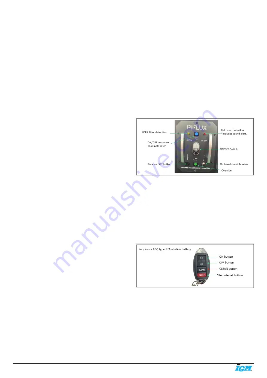
High Frequency Remote Control Receiver and Manual Switch
HEPA Filter detection
– will illuminate when filter cleans (automatic
cleaning/override)
Full drum detection
– when drum is full, buzzer* will constantly sound off
and light will illuminate.
*When the drum is close to 70%-80% full; intermittent buzzing will occur;
this is a normal state.
ON/OFF Switch
– turns cyclone ON or OFF.
On board circuit breaker – Pops out if machine overloads. Press to
reset.
Override
– Press for (3) seconds to activate override cleaning while
the
cyclone is ON. You can also activate this function by pressing the CLEAN
button on the hand held remote for (3) seconds.
Receiver SET button
– Used to program receiver.
ON/OFF Illuminate drum
– controls the LED light on the drum lid to
illuminate inside the drum for visuals of the dust level.
Hand held remote controller
*Used to match up a new hand held control with the remote switch
PROGRAMMING THE REMOTE CONTROL
1. Ensure the machine is switch ON before programming the remote
control.
2. Press the black set button on the bottom of the remote switch until you
hear two beeps.
3. Press the Remote set button on your hand held controller
simultaneously with the black button until you hear three beeps to
complete the set up.


