


www.igmtools.com
5
Operating manual EN
5.3 Connection to power
Before connecting the machine to electricity
network, make sure that the main switch is in the ‘0’
OFF (turned off) position.
The plug, as well as the cable must meet standards.
Line voltage must be consistent with the label on the
power tool. Wiring and repairs of electrical parts may
be carried out only by a qualified electrician.
5.4 Dust Extraction
The trimmer has to be connected to an industrial dust
extractor before use. To connect, use the extraction
outlet (Note 6) Use a 25,4mm diameter hose. Some
shavings may be charged with static electricity and
remain “stuck” to material or power tool.
We recommend using a 2,5m
3
/s suction power.
Turn on the exhaustion before starting the machine
6. PREPARATION FOR OPERATION
Before operation, make sure the workpiece is firmly
stationed.
Connect the dust extraction to the outlet.
Check if the rotation of the power tool does not
exceed the limit of the router bit.
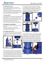
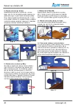
6.1 Assembly of the Trimmer
First separate the motor and the trimmer. Completely
unscrew the quick release lever and remove it. Now,
by pulling down you can remove the motor from the
trimmer.
fig. 2
Select the adequate tool for trimming. Use 22mm and
13mm wrenches to release the hex nut (fig.3). Based
on the selected router/cutter, choose a suitable collet
(6mm or 8mm). Make sure the collet and router bit are
clean and are not damaged. Now affix it to the power
tool (fig.4). Make sure the router bit is correctly placed
into the collet and is sufficiently pushed in according
to the mark on the arbor. Improper assembly may
cause danger in the form of vibration, or tool release.
Do not tighten the union bit, if the router bit is not
inserted, you will prevent damage to the collet. Use
22mm and 13mm wrenches to tighten the hex nut
and make sure it is thoroughly affixed (fig.5).
fig. 3
fig. 4
fig. 5
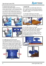
fig. 6
When the bit is installed, re-insert the support table
onto the motor in the arrow direction (fig.6). Put back
the quick release lever and tighten the nut. Adjust
the height of the supporting table on the body of
the motor (fig.7). Tighten the quick release lever in
the arrow direction (fig.8). to lock it. The supplied R2
radius router bit is ideal for a 2mm edge. The router
bit radius should match the thickness of the edge.
1.
2.
3.
fig. 7
fig. 8