background image

CHECK FAULTS

When abnormal situation such as failure of welding, unstable arc, poor welding result, do not

consider that it must be some faults.

The machine may be well but just some reasons cause abnormality such as that some connectors

are loosened, forget to turn on the switch, wrong setting, broken cable and gas pipe, etc. So before

maintenance, Please check it up first, some problem may be solved.

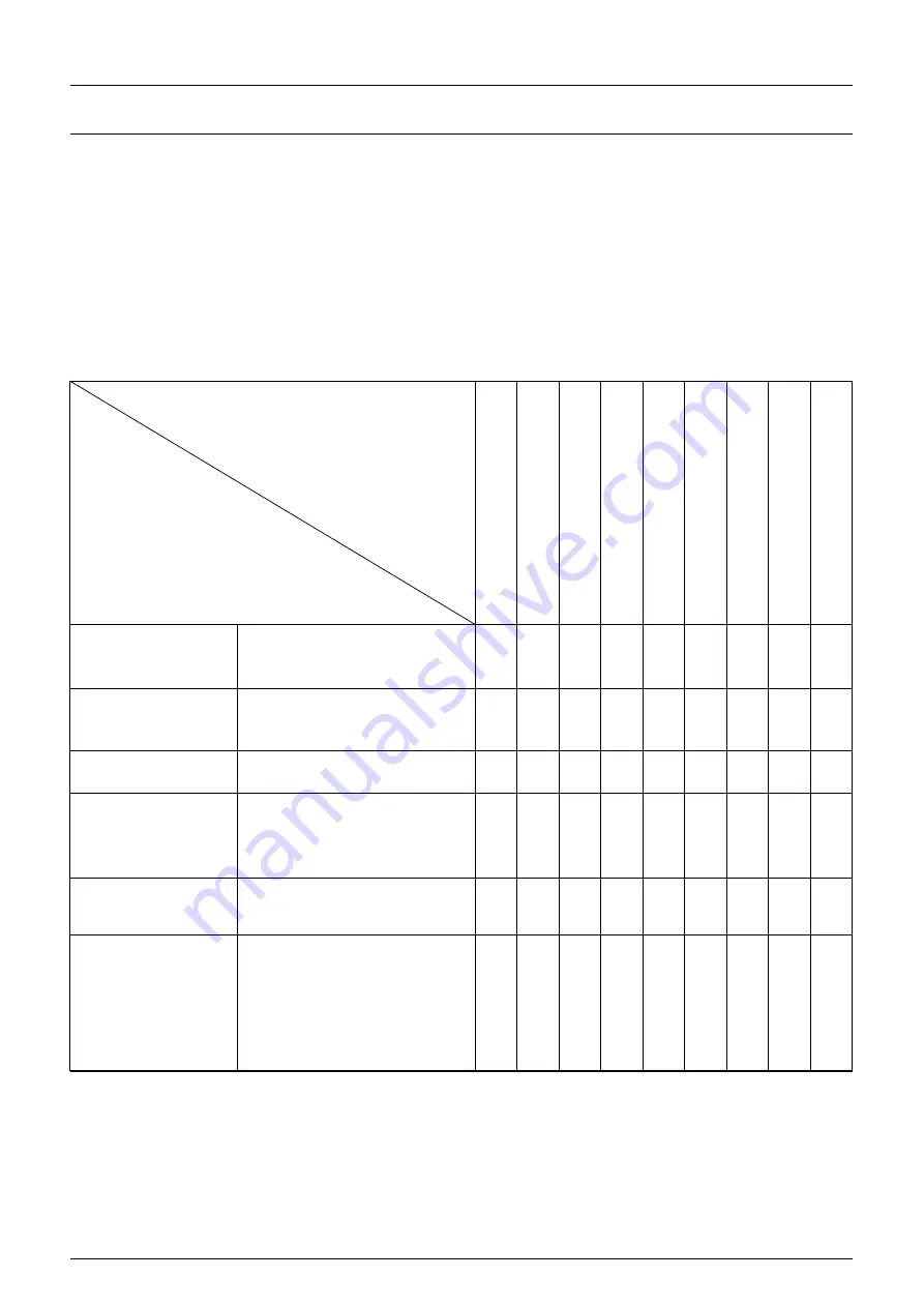
The following is earlier checking diagram by this way. In the top right corner item you can find the

problem, please check according to the diagram for the one with “O” mark.

EARLIER CHECKING DIAGRAM FOR THE ABNORMAL

The abnormal

Place and item to be checked

N

o

arc

ing

N

o

ga

s

Ca

n

no

tS

en

d

w

ire

Po

or

A

rcin

g

init

iati

on

U

nst

ab

le

arc

W

eld

ing

m

arg

in

un

cle

an

W

ire

an

d

M

ate

ria

lc

on

glu

tin

ate

d

W

ire

lin

ks

Ele

ctr

ic

lea

din

g

ho

le

fco

n

co

ng

luti

na

ted

H

av

e

air

ho

le

Power supply box

input protective

set

1

connected or not

2

fuse broken

3

connector loosen

Input cable

1

Broken or not

2

Connector loosen

3

overheat

Power

1

Switched or not

2

lack phase

Gas cylinder&adjuster

1

open cover

2

remains of gas

3

flow setting volume

4

Connecting point loosen

Gas pipe (access from

the high-pressure

cylinder to torch)

1

Connecting point loosen

2

Pipe broken

Wire sending

equipment

1

Wheel and leading tube not

match

2

Wheel broken, slot blocked

or lack

3

Over pressing or loosen,

powder store up in entrance

of SUS tube

Summary of Contents for MIG-160

Page 1: ...IGBT INVERTER MIG WELDER USER S MANUAL MIG 1KG Series MIG DS Series MIG 5KG A Series MIG 5KG B Series NOTE Please read this manual carefully before use ...

Page 2: ...t of the gas When arc welding air extractor should be used to prevent from breathing gas Arc radiation Harmful to your eye and burn your skin Use suitable helmet and light filter wear protective garment to protect eye and body Use suitable helmet or curtain to protect looker on Fire Welding spark may cause fire make sure the welding area no tinder around Noise extreme noise harmful to ear Use ear ...

Page 3: ...f the machine is equipped with electronic reactor circuit which can accurately control the process of the electric short transition and blending transition and result excellent welding characteristic Comparing with synergic welding machine and other machine it has the following advantages stable wire speed compact power saving no electromagnetic noise Continuous and stable operation with small cur...

Page 4: ...0 Output current A 110V 30 120 30 130 40 140 40 150 No load Voltage V 16 5 22 0 16 5 23 0 16 5 24 0 16 5 25 5 25 Duty cycle 60 60 60 60 Power factor 0 93 0 93 0 93 0 93 Efficiency 85 85 85 85 Wire Feeder Inside Inside Inside Inside Wire speed m min 2 5 15 2 5 14 2 5 14 2 5 14 Wire speed m min 110V 2 5 10 3 8 3 8 3 8 Wire diameter mm 0 6 0 8 0 9 0 8 0 9 1 0 0 8 0 9 1 0 0 8 0 9 1 0 Protection Degree...

Page 5: ...Method 9 Polarity Conversion Cable Connector Note VERY IMPORTANT A When use gas welding solid wire Install 9 into 11 and install earth clamp with cable into 12 B When use gasless welding Flux wire Install 9 into 12 and install earth clamp with cable into 11 10 MIG Welding Torch 11 ositive Polarity Connector 12 Negative Polarity Connector 13 Parameter Table 14 Power Switch for ON OFF 15 Gas Hose In...

Page 6: ...SPL MIG SYN MIG stp Step for Torch control mode 2T 4T SPL MIG SYN MIG hs hot start 0 10A SPL MIG SYN MIG MMA rin arc start speed 0 10ms SPL MIG SYN MIG bbt burnback 0 1s SPL MIG SYN MIG dIG Arc Force 0 10A MMA Vrd Voltage Reduction Device On Off MMA Ant Anti stick On Off MMA ...

Page 7: ...ed Adjustment 11 Polarity Conversion Cable Connector Note VERY IMPORTANT A When use gas welding solid wire Install 11 into 12 and install earth clamp with cable into 13 A When use gasless welding Flux wire Install 11 into 13 and install earth clamp with cable into 12 12 Positive Polarity Connector 13 Negative Polarity Connector 14 MIG Welding Torch 15 Power Switch for ON OFF 16 Gas Hose Inlet Conn...

Page 8: ...MMA mode can adjust welding current from small to big MIG Burnback Function It can remove small ball after stopping welding MIG Voltage Adjustment While MIG mode can adjust voltage from low to high MIG Wire Speed Adjustment stepless adjusment from slow to fast Polarity Conversion Cable Connector When gas welding solid wire install this into Positive Polarity Connector When gasless welding Flux wir...

Page 9: ...er security Installment when use gas welding solid wire 1 Connect the gas bottle with CO2 regulator flow meter and the Input Gas Connector behind the machine via gas hose 2 Insert the cable connector of earth cable into the socket in the front panel 3 Set the welding wire spool on the wheel axis the wheel hole should be matched with the wheel fixer 4 Choose wire slot according to wire size 5 Loose...

Page 10: ...2 Set the welding wire spool on the wheel axis the wheel hole should be matched with the wheel fixer 3 Choose wire slot according to wire size 4 Loosen the screw of wire pressing wheel put the wire into slot via wire lead tube tune the Wire pressing wheel to fix wire from gliding but pressure should be suitable in case the wire distorts and affects wire sending 5 Wire roller should turn clockwise ...

Page 11: ...should make sure the working area is adequately ventilated It is important for the performance and the longevity of the machine 2 Do not over load The operator should remember to watch the max duty current Response to the selected duty cycle Keep welding current is not exceed max duty cycle current Over load current will damage and burn up machine 3 No over voltage Power voltage can be found in di...

Page 12: ...ION Before Maintenance and checking power must be turned off and before Opening the housing make sure the power plug is pulled off 1 Remove dust by dry and clean compressed air regularly if welding machine is operating in environment where is polluted with smokes and pollution air the machine need remove dust everyday 2 Pressure of compressed air must be inside the reasonable arrangement in order ...

Page 13: ...rch is broken 4 Control circuit is broken Power indicator is lit fan works abnormal indicator is lit 1 Maybe it is overheated protection please turn off machine first then turn on the machine again after abnormal indicator is off 2 Maybe it is overheated protection wait for 2 3 minutes 3 Maybe inverter circuit is in fault 1 If abnormal indicator is still lit some of IGBT is damaged on the main boa...

Page 14: ... Place and item to be checked No arcing No gas Can not Send wire Poor Arcing initiation Unstable arc Welding margin unclean Wire and Material conglutinated Wire links Electric leading hole fcon conglutinated Have air hole Power supply box input protective set 1 connected or not 2 fuse broken 3 connector loosen 〇 〇 〇 〇 〇 〇 Input cable 1 Broken or not 2 Connector loosen 3 overheat 〇 〇 〇 〇 〇 〇 Power ...

Page 15: ...rew thread damage 2 damage of its head and hole blocked nor not Reason of unstable arc and broken arc Wire sending tube 1 check the extended size of the pipe Have to be changed when less than 6mm when the extended part too small the arc will be unstable 2 wire diameter and the tube inner diameter match or not Reason of unstable arc please use the suitable tube 3 partial winding and extended Reason...

Page 16: ...nding Position Checking keys Remarks Torch cable 1 If torch cable over bended 2 If the metal connecting point of mobile plug loosen 1 Cause poor wire sending 2 Unstable arc if cable over bended Output cable 1 Wearing out of the cable insulated material 2 Cable connecting head naked insulation damage or loosen the end of power supply and cable of main material connecting point For life security and...

Reviews: