


P/N 1073642-EN
• REV
D
• ISS
03JUL22
3 / 4
3.
Use the screws to screw the wall
-
mount plate on the
industrial gigabit Ethernet switch
.
4.
Use the hook holes at the corners of the wall
-
mount plate
to hang the industrial gigabit Ethernet switch
on the wall.
5
.
To remove the wall
-
mount plate, reverse the steps above.
Starting web management
The section describes
how to start
up the
web management
function for
the industrial managed switch
. N
ote that the
industrial managed switch
is configured through an Ethernet
connection
.
Ensure that the manager computer is
set to
the
same
IP subnet address
.
For
example, if the default IP address of the industrial
managed switch
is
192.168.0.100
, then the manager computer
should be set to
192.168.0
.x
(where x is a number between 1
and 254, except 100), and the default subnet mask is
255.255.255.0.
Figure 3: IP management diagram
Logging in to the industrial managed switch
1.
Use
the
Internet Explorer
11
.0 or later
web browser
and
type the
IP address http://192.168.
0.100
(the factory
-
default IP address) to access the web interface.
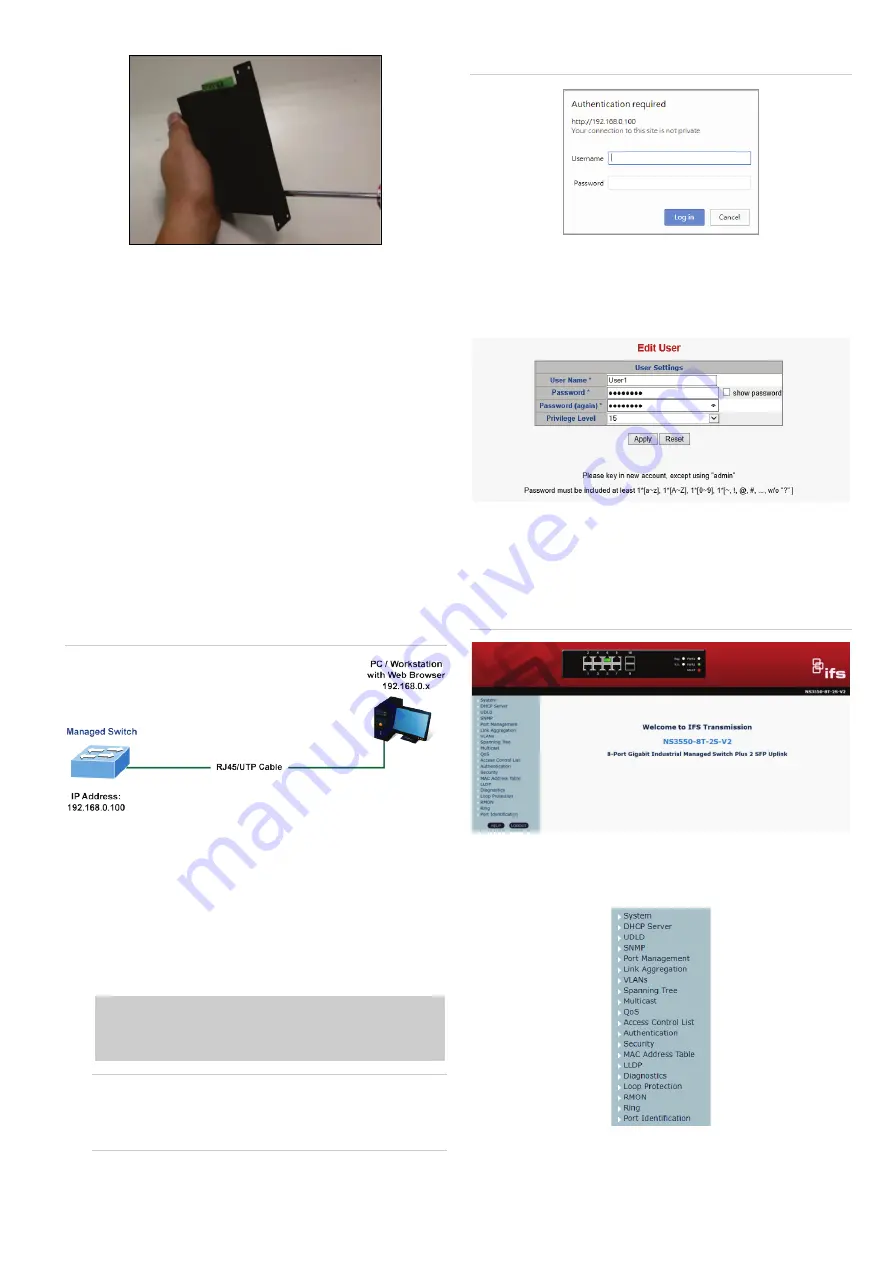
2.
When the following dialog box
appears, type
the default
user name
“
admin
”
and password “admin
”
(or the
password you have changed before)
as shown in
Figure
4
below
.
Default IP Address:
192.168.0.100
Default User
N
ame:
admin
Default Password
:
admin
Note
:
Before connecting to a TruVision Navigator video
surveillance system network, the default IP address must
be changed to the IP address assigned for TruNav by the
network administrator.
Figure 4: Login screen
3.
Click
OK
to begin the process of changing the default
username and password
.
4.
Type a new username and password in the Edit User
page, following the guidelines as shown. Click
Apply
.
5
.
When the success window appears, click
OK
.
6.
After typing
the new
username and password
in the login
window, the
main screen appears as
shown in
Figure
5
below
.
Figure 5: Main web interface screen
7.
The
switch menu on the left side of the web page permits
access to all the functions
and
status
provided by the
industrial managed switch
.
Refer to the
U
ser Manual for further information about using
the web management interface.


