OPD101
15
6 Electrical connection
The device must be connected by a qualified electrician.
u
The national and international regulations for the installation of electrical equipment must be
adhered to.
u
Ensure voltage supply to EN 50178, SELV, PELV.
OPD101: cULus, Supply Class 2
u
Disconnect power.
u
Connect the unit as follows:
4
2
1
3
5
L
1
2
4
5
3
OUT2
OUT1
IN1
L+
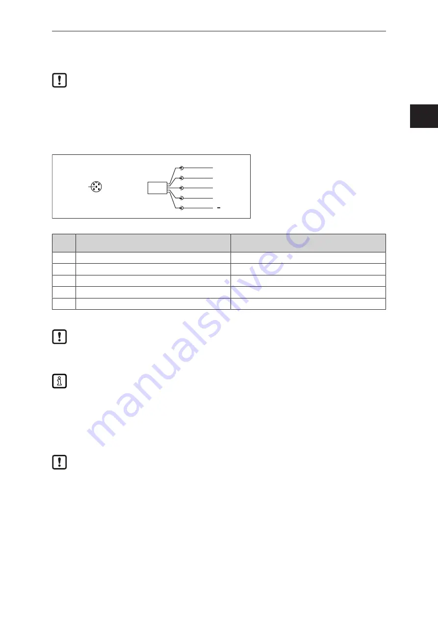
Fig. 7: Wiring diagram (colours to DIN EN 60947-5-2)
1 =
BN (brown)
2 =
WH (white)
3 =
BU (blue)
4 =
BK (black)
5 =
GR (grey)
Pin
Continuous mode
(factory setting)
Triggered mode
1
VDD
VDD
2
OUT2 = switching output
OUT2 = ready signal (switching output)
3
GND
GND
4
OUT1 = switching output / IO-Link
OUT1 = switching output / IO-Link
5
Laser ON / OFF*
Trigger input of the PLC
*) The function is activated / deactivated via IO-Link or the ifm parameter setting software.
In the operating mode “Continuous mode”, OUT1 and OUT2 are configured as complementary
switching outputs. Continuous mode (
In the operating mode “Triggered mode”, OUT2 is configured as ready signal. Triggered mode
(
Complementary outputs transmit the same sensor information with oppositional logic levels.
This means that both an NC and NO switching output are available at the same time.
OUT1 can e.g. be used for the detection of good parts, OUT2 for the detection of bad parts.
6.1 Operation with IO-Link master
The unit is compatible with IO-Link master port class A (type A).
For operation with IO-Link master port class B (type B) observe the following:
As a standard, the unit is not compatible with master port class B (type B). Pin 2 and pin 5 are
used for manufacturer-specific functions. That means that the main supply voltage of the unit
and the additional voltage supply (master port class B on pins 2/5) are not electrically isolated.
With the following configuration, the unit can be used with master port class B:
•
Connect unit and IO-Link master via 3 wires: Connect pins 1, 3 and 4 of the unit with the IO-Link
master (do not connect pins 2 and 5).
GB


