LR7009
Electronic level sensor
12
d
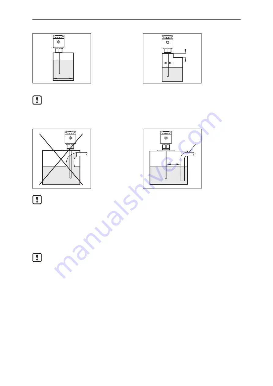
Fig. 5: Installation on a pipe
d
h
Fig. 6: Installation in a boss
Although the device can be installed in a boss: installation in a flat tank lid is recommended, as
a boss will impede the distribution of the microwaves.
Do not install the device in the immediate vicinity of a fill opening. If possible, install a fill pipe (A) in the
tank. Minimum distance between the fill pipe and the rod = 50 mm; higher for probe lengths > 70 cm
and in case of heavy soiling.
50mm
A
To avoid incorrect measurements in case of heavy foam formation and turbulence:
u
If possible, install the sensor in a steady area.
Examples of how to create a steady area:
u
Use of a coaxial probe (only for clean, low-viscosity media)
u
Installation in bypass or still pipe
u
Separation of the installation location by metal sheets / perforated sheets (without figure)
Min. diameter of the bypass and still pipe: d = 100 mm.
The upper access to the steady area (Fig. A / B) must be above the max. level. The lower
access (Fig. C / D) or the area with perforated sheet etc. must be below the min. level. This
ensures that neither foam nor turbulence impact the sensor zone. Besides, the use of
perforated sheets or the like can help to avoid soiling (e.g. by metal swarf, particles).


