background image

10

8.1.2 The switched state

If the target is in the enable zone and if there is no sensor error, both outputs A1
and A2 (OSSDs) are enabled (logic "1").

8.1.3 Output characteristics

The interface of the devices complies with interface type C class 1 according to
the ZVEI position paper CB24I Ed. 2.0.x.
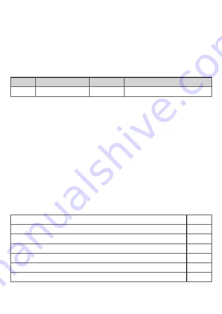
Interface type

Suitable interface type

Source

C1

Receiver

C1

Tab. 1: Identification key

8.1.4 Cross fault / short circuit

• A cross fault between both outputs (A1 and A2) is detected by the fail-safe

sensor and results in the outputs (OSSD) being switched off after 4 s at the
latest. The outputs A1 and A2 remain switched off until the error has been
removed or a voltage reset has been carried out.

• A cross fault (short circuit) between output A2 and the supply voltage results in

the other output A1 being switched off after 4 s at the latest.

• The subsequent safety-related logic unit (e.g. safe PLC or safety relay) must be

able to detect faults via dual-channel evaluation (e.g. "stuck-at faults"). The
monitored hazardous area may only be enabled if both inputs of the safety-
related logic unit were previously switched off at the same time (logic "0").

8.2 Response times

Response time on safety request (removal from the enable zone)

≤ 5 ms

Response time when approaching the enable zone (enable time)

≤ 5 ms

Risk time / response time for safety-related faults

≤ 100 ms

Simultaneity of switching on and off of the outputs in case of a safety request

≤ 1 ms

Test pulse duration t

i

 on A1 and A2

≤ 1 ms

Test pulse interval T1 on A1

< 4 s

Test pulse interval T2 on A2

< 2 s

Summary of Contents for GI854S

Page 1: ...Original operating instructions Fail safe inductive sensor GI854S 80289626 01 12 2021 GB...

Page 2: ...on 6 5 1 Enable zone 6 5 2 Switch on curve Sao 7 6 Mounting 8 7 Electrical connection 9 8 Operation 9 8 1 Switching state of the outputs 9 8 1 1 The safe state 9 8 1 2 The switched state 10 8 1 3 Outp...

Page 3: ...ry w Death or serious irreversible injuries may result 2 Safety instructions The unit described can be installed as a subcomponent in a safety related system The operator is responsible for the safety...

Page 4: ...this document before setting up the product and keep it during the entire service life The product must be suitable for the corresponding applications and environmental conditions without any restrict...

Page 5: ...ocument maintenance actions time persons etc u Adhere to EN 14 119 for interlocking devices associated with guards u Adhere to the principle of normally closed operation for all external safety circui...

Page 6: ...tion The device has been certified by T VNord 5 Function 2 5 0 1 3 4 1 1 LED yellow 2 Safe switch off distance sao 3 Inadmissible zone 4 Enable zone 5 Target 5 1 Enable zone The outputs OSSDs are only...

Page 7: ...f distance for specific materials Material Safe switch off distance sao mm FE360 ST37 0 12 stainless steel 0 8 4 aluminium 0 4 8 brass 0 4 8 copper 0 3 6 Typical values for damping with a reference ta...

Page 8: ...u Tighten the supplied fastening nuts to a maximum tightening torque of 50 Nm WARNING Failure of the safety function If the sensor or the target comes loose in its fixture the sensor can no longer fu...

Page 9: ...any independently supplied relay load circuits u Supply voltage connect L to pin 1 and L to pin 3 of the connector If used in accordance with EN 61131 2 the supply voltage including residual ripple mu...

Page 10: ...has been carried out A cross fault short circuit between output A2 and the supply voltage results in the other output A1 being switched off after 4 s at the latest The subsequent safety related logic...

Page 11: ...oth outputs switched off 0 0 overvoltage both outputs switched off 0 0 sensor fault 10 Troubleshooting one output or both outputs switched off 0 1 0 1 0 0 target is at safe switch off distance from th...

Page 12: ...E I J K4 2 0 K7 L 9 2 M N O P 7 4 B 6 Q F 1 2 0 0 R G I 1 1 N O ST A H 4 B 6 U V W X 6 YZZ9 8 7 8 G 2 2 F 0 G 2 0 2 1 R G G 2 G 2 G 2 2 R 2 0 F 1 2 1 2 0 2 G 0 R KG G 2 1 2 0 2 1 2 G G 2 1 9 8 7 9 7 7...

Page 13: ...A O V F W IP Q XY S 4 A EF G F 0 2 2 2 W G P 2 1 1 4 EF G F N 2 2 7 5 R G 2 O 9 Z 4 4 U 4 7 G F 1 W G 4 7 F G W 1 EN 2 0 G W 1 M2 H B 2 G 2 N 2 0 P 2 H Q S 7 A 8 _ 9 2 Y Q S 7 4 B 6 2 1 O 01 2 1 J 2 L...

Page 14: ...W J 2 02 1 2 0 4 Y S 6 A 6 02 1 0 7 7 G 1 2 Y A I J 2 1 R _ G _ G 5 5 8 A 2 _ Jab 9b 5 Y W b 02 1 0 7 7 G 1 2 S 6 I J O 0 2 G G0 1 R G 1 c 4 6 d 5 Y _e X b 2 O 0 2 bLX 5 _99 G 1 _O 0 5 Y L _ JW 2 1 1...

Page 15: ...1 4 7 2 L 2 L 5 6 1 H U H 6 8 O 2 G Q Q FP Q 9 6 6 A 7 6 O 2 11 2 9 I A A I 8 7 I 7 A W 4 A B B B L A A A RS X P 6 A 1 V T U 1 Z 4 2 H T G Z L 2 1 2 0 2 0 1 9 I A A I 8 7 I 5 6 Z J W 4 A B B B 7 A A A...

Page 16: ...2 0 Z 1 1 2 W S Z S 9O X 0 XW 9 Z K 1 W 2 1 1 X Y 2 0 U K F G _ 6 A 8a9 7 b a 7 8 c 9d O1 M 2 L O1 M 2 L 1 X 1 2 K 1 5 S 9Oe L X f 8 1 1 K M M 0 K 1 W 7 gd7 h i 2 1 2 2 1 K K 1 K M M 0 Z Q K 1 0 L K 1...

Page 17: ...17 01 2 3 4 5 67 8 97 8 8 01 1 4 3 51 5 0 1 2 3 4 5 6 4 7 8 91 1 9 8 6 5 7 A B A 8 B 7 A 7 4 C 8 4 D 1 2 E 2 0 F...

Page 18: ...vice in an environmentally friendly way in accordance with the applicable national regulations 12 Terms and abbreviations OSSD Output Signal Switching Device Output signal switch element PDDB Proximit...

Reviews: