


14
6 Electrical connection
The unit must be connected by a qualified electrician�
The national and international regulations for the installation of electrical
equipment must be adhered to�
Voltage supply according to EN 50178, SELV, PELV�
The unit is supplied with 24 V DC (18���32 V DC) low voltage�
The voltage supply must comply with the provisions of protective low
voltage EN 50178, SELV, PELV�
►
Disconnect power�
►
Connect the unit as follows:
4
2
1
3
5
BK: black
BN: brown
BU: blue
GY: grey
WH: white
Colours to DIN EN 60947-5-2
Pin 1
L+
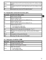
Pin 2 (OUT2)
analogue output
Pin 3
L-
Pin 4 (OUT1)
switching output
IO-Link
Pin 5
test input
►
Use a screened cable� The screen of the cable must be connected to
the sensor housing�
When inductive loads are switched:
►
Use a free wheel diode�


