background image

CONTRÔLEUR

AL-3

63

FRAN

Ç

AIS

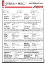
Parameterliste / Parameter list / Table des paramètres  

MOD

Mode

1CH

A-B

2CH

A+B

Systemparameter / System parameters / Paramètres de système

IN1

Input 1 (type)

4-20 mA

0-20 mA

IN2

Input 2 (type)

4-20 mA

0-20 mA

INP

Input 1/2 (type)

4-20 mA

0-20 mA

DH1

Display High Input 1

20.0

DH2

Display High Input 2

20.0

DHI

Display High Input 1/2

20.0

DL1

Display Low Input 1

4.0

DL2

Display Low Input 2

4.0

DLO

Display Low Input 1/2

4.0

FO1

Function Output 1

(1)

(3)

(5)

(2)

(4)

(6)

FO2

Function Output 2

(1)

(3)

(5)

(2)

(4)

(6)

SO1

Store Output 1

OFF

Front

FuE

SO2

Store Output 2

OFF

Front

FuE

FS1

Function Signal Evaluation Input 1

OFF

on

FS2

Function Signal Evaluation Input 2

OFF

on

DM1

Dimension Input 1

mA

°C

bar

DM2

Dimension Input 2

mA

°C

bar

DIM

Dimension Input 1/2

mA

°C

bar

AO3

Analog Output 3

0-20 mA

4-20 mA

Applikationsparameter / Application parameters / Paramètres d'application

SP1

Switch Point Output 1

6.0

SP2

Switch Point Output 2

18.0

HY1

Hysteresis Output 1

10

% (SP1)

HY2

Hysteresis Output 2

10

% (SP2)

ST1

Start-Up-Delay Output 1

0.0

s

ST2

Start-Up-Delay Output 2

0.0

s

DT1

Delay Time Output 1

0.0

s

DT2

Delay Time Output 2

0.0

s

FT1

Fleeting Time Output 1

0.0

s

FT2

Fleeting Time Output 2

0.0

s

AE3

Analog End Output 3

20.0

AS3

Analog Start Output 3

0.0

= Voreinstellung
= factory setting

Nom

= réglage en usine

Date

Parameterliste siehe auch / see also parameter list / cf. table des param

è

tr

es 

www

.ifm-electr

onic.com 

DL2003

Summary of Contents for DL2003

Page 1: ...ce d utilisation Monitor AL 3 Contrôleur AL 3 DL2003 1 4 6 5 2 19 20 21 22 23 24 13 14 15 16 17 18 3 9 7 8 10 11 12 MONITOR AL 3 Analog Limit In1 CH1CH2 CH3 CH4 RUN PRG TST KEY In2 Out1 Out2 COM R DEUTSCH ENGLISH FRANÇAIS Sachnr 7390444 02 10 2006 ...

Page 2: ...versorgung Seite 7 Anschluss der Sensoren und Transmitter Seite 8 Eingang Reset 1 2 Seite 8 Eingang Release 1 2 Seite 8 Lastkreis Relaisausgang Out1 2 Seite 9 Lastkreis Transistor Out1 2 Seite 9 Analogausgang Out3 Seite 9 6 Signalüberwachung Seite 9 7 Navigation und Parameterbeschreibung Seite 10 Systemparameter Seite 12 Applikationsparameter Seite 14 8 Programmieren Seite 15 Programmierbeispiel D...

Page 3: ...ät muss für den bestimmungsgemäßen Betrieb in ein nur mit Werkzeug zu öffnendes Gehäuse Schutzart IP 40 oder höher oder einen geschlossenen Schaltschrank eingebaut werden Wird das Gerät mit einer externen 24 V Gleichspannung versorgt muss diese ex tern gemäß den Kriterien für sichere Kleinspannung SELV erzeugt und zugeführt werden da diese Spannung ohne weitere Maßnahmen in der Nähe der Bedienele ...

Page 4: ... ein programmierbarer analoger Grenzwertschalter zur Aus wertung von physikalischen Größen die sich aus analogen Normsignalen ableiten lassen Die Funktion des Gerätes ist durch die Einstellmöglichkeiten der verschiede ner Parameter in weiten Grenzen variabel und kann so an die jeweilige Applikation angepasst werden Einsatzbereiche sind z B die Grenzwertüberwachung von Strömung Druck Temperatur ode...

Page 5: ...usgegeben werden Die Ausgänge schalten entsprechend der eingestellten Parameterwerte und Funktionen Die Teach Funktion ermöglicht die Zuordnung eines Signal Istwertes zu einem Schaltpunkt und die Wertebereicherfassung des Analogausganges Der Monitor AL 3 ist nur einkanalig aufgebaut Durch eine elektrische Ver bindung des Ausgangs von zwei oder mehreren Geräten mit dem Ziel eines redundanten Schalt...

Page 6: ...ge Parameterkürzel und Einheiten 3 stellig alphanumerisch 2 Tasten Wahl der Istwertanzeige Parameteranwahl Einstellen der Parameterwerte 3 Taste Anwahl des Betriebsmodus Übernahme des Parameterwertes Frontreset 4 LED In1 2 gelb Eingangssignale LEDs aktiv wenn In1 2 0 1 mA Ein Signal im Arbeitsbereich Langsam blinkend Signal im Warnbereich Schnell blinkend Signal im Fehlerbereich 5 LED Out1 2 grün ...

Page 7: ...men 1 2 24 V DC Die Klemmen 1 2 der 24 V DC Versorgung sind direkt mit den Klemmen der Sen sorversorgung verbunden Daher müssen für DC Versorgung die SELV Kriterien ein gehalten werden Schutzkleinspannung Stromkreis galvanisch getrennt von ande ren Stromkreisen nicht geerdet Die Versorgungsleitung muss extern gemäß dem verwendeten Querschnitt abge sichert sein max 16 A MONITOR AL 3 7 DEUTSCH 1 2 3...

Page 8: ...nd Transmitter Die Klemme 10 kann für die Transmitterversorgung die Ansteuerung des Reset Re lase Eingangs und die Speisung der Transistorausgänge genutzt werden Eingang Reset 1 2 Externer Reset Ein Impuls 24 V DC auf Klemme 18 setzt bei aktivierter Speicherfunktion Para meter SOx den im Fehlerfall gespeicherten Relaiszustand zurück Ein dauerhaftes Betätigen hat keinen Einfluss auf die Überwachung...

Page 9: ...ert werden Analogausgang PWM Out 3 Der Analogausgang hat keine galvanische Trennung zur Sensor Transmitter Versorgung und der 24 V DC Versorgungsspannung An den Analogausgang dür fen keine berührgefährlichen Stromkreise angeschlossen werden 6 Signalüberwachung Der Messbereich der Eingangssignale ist unterteilt in den Arbeitsbereich den Warn und den Fehlerbereich Um die Signalüberwachung zu nutzen ...

Page 10: ...i der Inbetriebnahme eingestellt Die Parameter unterhalb dieser Einträge stellen Applikationsparameter dar Sie wer den ggf häufiger ein bzw umgestellt 1CH und 2CH Modus MOD VER IN1 DH1 DL1 FO1 SO1 FS1 DM1 FT1 DT1 ST1 HY1 SP1 IN2 DH2 DL2 FO2 SO2 FS2 DM2 FT2 DT2 ST2 HY2 SP2 AO3 AS3 AE3 Istwert Eingang 1 C Istwert Eingang 2 C Istwert Ausgang 3 C Anzeige zeigt wahlweise RUN Modus Parameterbereich und ...

Page 11: ...dung von 2 physikalisch identischen Prozessgrößen s Seite 5 Prinzip Vergleicher Modus A B A B MONITOR AL 3 11 DEUTSCH MOD VER Istwert Eingang 1 bar Istwert Eingang 2 bar A B A B Dbar Istwert Ausgang 3 Dbar INP DHI DLO FO1 SO1 FS1 DIM FT1 DT1 ST1 HY1 SP1 FO2 SO2 FS2 FT2 DT2 ST2 HY2 SP2 AO3 AS3 AE3 Anzeige zeigt wahlweise RUN Modus Parameterbereich und PRG Modus zurück in den RUN Modus System parame...

Page 12: ...l 4 20 Auswahl des Eingangssignales im 1CH 2CH bzw A B A B Modus 0 20 Werte 4 20 0 20 mA Voreinstellung 4 20 mA DHx DHI Display High Endwert des Messbereiches Entspricht dem realen Messwert bei 20 mA Werte 1CH 2CH Mode 9999 0 9999 0 A B A B Mode 4999 0 4999 0 Voreinstellung 20 0 DLx DLO Display Low Anfangswert des Messbereiches Entspricht dem realen Messwert bei 0 oder 4 mA Werte 1CH 2CH Mode 9999...

Page 13: ...ignal und Leitungsüberwachung OFF Inaktiv on Aktiv Schaltverhalten der Relaisausgänge mit inaktivem und aktivem Parameter FSx Beispiel Schaltfunktion 1 und 2 Werte OFF on Voreinstellung OFF Signal und Leitungsüberwachung inaktiv DMx DIM Dimension Einheit Werte C bar lit mA keine Einheit Voreinstellung mA AO3 Analog Out3 Analogausgang 4 20 Strombereich des analogen Ausgangsignals 0 20 Werte 4 20 0 ...

Page 14: ...g 0 0 s Anlaufüberbrückung inaktiv DTx Delay Time Verzögerungszeit Ausgang 1 2 Ermöglicht ein verzögertes Schalten des jeweiligen Ausgangs Bei einem Wert 0 0 s schaltet der Ausgang erst wenn der Zustand der Schaltpunkt über oder Schaltpunktunterschreitung länger als die hier eingestellte Zeit andauert Werte 0 0 1000 0 s Voreinstellung 0 0 s keine Verzögerungszeit FTx Fleeting Time Wischfunktion Au...

Page 15: ... Programmierbeispiel DT2 Delay Time Ausgang 2 MONITOR AL 3 15 DEUTSCH Vorgang Display Wechsel vom RUN Modus in den Parameterbereich hier 2 Taste 3 x kurz betätigen Display zeigt den 2 Parameterbereich Anwahl des gewünschten Parameters hier DT2 Taste so oft betätigen bis im Display der Parameter DT2 mit dem aktuell eingestellten Wert erscheint hier Voreinstellung 0 0 Wechsel in den PRG Modus Taste ...

Page 16: ...en angezeigt und dem ausgewählten Parameter zugeord net werden Zum Teachen eines aktuellen Messwertes werden zunächst die gleichen Programm schritte wie bei einer normalen Programmierung durchgeführt 1 Wechsel vom RUN Modus in den Parameterbereich 1 2 oder 3 Taste 2 Anwahl des gewünschten Parameters SP1 SP2 AE3 oder AS3 Tasten 3 Wechsel in den PRG Modus Taste PRG Indikator sichtbar Parameterkürzel...

Page 17: ... Die werkseitigen Grundeinstellungen können durch gleichzeitiges Betätigen der und Taste während des Netz Einschaltens zurückgeholt werden Dabei gehen al le eingegebenen Parameterwerte verloren KEY Funktion Um Fehleingaben zu verhindern lässt sich das Gerät verriegeln Verriegeln Tasten gleichzeitig betätigen und festhalten Der KEY Indikator blinkt Tasten loslassen wenn der KEY Indikator dauerhaft ...

Page 18: ...DLO Display Low 0 Min Messwert des Gebers FO1 Function Output 1 4 Relais 1 fällt ab bei Überschreiten von SP1 schaltet zurück bei SP1 HY1 FO2 Function Output 2 4 Relais 2 fällt ab bei Überschreiten von SP2 schaltet zurück bei SP2 HY2 SP1 Switch point Output 1 5 Druckdifferenz bar 1 Grenzwert 1 SP2 Switch point Output 2 15 Druckdifferenz bar 2 Grenzwert 2 HY1 2 Hysteresis for SP1 2 10 Rückschaltpun...

Page 19: ...altspannung Schaltstrom 12 30 V DC 20 max 15 mA Analogausgang puls weiten moduliert PWM Genauigkeit 1 Strom 0 4 20 mA max 20 5 mA Bürde max 500 Ohm Reset Release Eingänge Externe Hilfsspannung 24 V DC Stromaufnahme typ 2 5 mA Schaltpunkt für PNP Schaltung 11 V 6 mA Gerätedaten Klemmschienengehäuse Kunststoff Abmessungen H x B x T 78 x 45 x 120 mm Gewicht 500 g Schutzart Gehäuse Klemmen IP 50 IP 20...

Page 20: ...Gerät von einer Fachkraft nach dem Abschalten aller angeschlossenen Stromkreise mit einem trockenen Tuch gereinigt werden Entsorgen Sie das Gerät nach Gebrauch umweltgerecht gemäß den gültigen nationalen Bestimmungen MONITOR AL 3 20 13E J sensor supply 10 100n UBB 24 V DC 100E In1 5 100E 100n 24k2 V 1 9 100E In2 100E 100n 24k2 V 1 9 6 Analog GND GND 4 11 sensor supply 45 78 1 4 6 5 2 19 20 21 22 2...

Page 21: ... Input 1 OFF on FS2 Function Signal Evaluation Input 2 OFF on DM1 Dimension Input 1 mA C bar DM2 Dimension Input 2 mA C bar DIM Dimension Input 1 2 mA C bar AO3 Analog Output 3 0 20 mA 4 20 mA Applikationsparameter Application parameters Paramètres d application SP1 Switch Point Output 1 6 0 SP2 Switch Point Output 2 18 0 HY1 Hysteresis Output 1 10 SP1 HY2 Hysteresis Output 2 10 SP2 ST1 Start Up D...

Page 22: ...pply page 27 Connection of the sensors and transmitters page 28 Input reset 1 2 page 28 Input release 1 2 page 28 Load circuit relay output Out1 2 page 29 Load circuit transistor Out1 2 page 29 Analogue output Out3 page 29 6 Signal monitoring page 29 7 Navigation and parameter description page 30 System parameters page 32 Application parameters page 34 8 Programming page 35 Programming example DT2...

Page 23: ...e correct operation the unit must be mounted in a housing pro tection rating IP40 or higher which can only be opened using a tool or in a closed control cabinet If the unit has an external 24 V DC supply this voltage must be generated and supplied externally according to the requirements for safe extra low voltage SELV since without further measures this voltage is supplied near the operating ele ...

Page 24: ...etting possibilities of the various parameters ensure that the function of the unit is variable within a great range of values and can thus be adapted to the individual application Applications are for example Limit monitoring of flow pressure temperature or level monitoring of the difference between inflow and return flow or monitoring of differential pressure MONITOR AL 3 24 Analogausgang IN1 Sc...

Page 25: ...d func tions The teach function enables the assignment of an actual signal value to a switch point and detection of the value range of the analogue output The AL 3 monitor only has one channel By means of an electrical connec tion of the output of two or several units to achieve a redundant circuit they can also be used for safety tasks The applicable technical standards must be ad hered to MONITO...

Page 26: ... mode acknowledgement of the parameter value front reset 4 LED In1 2 yellow Input signals LEDs active if In1 2 0 1 mA On Signal in the operating range Slowly flashing Signal in the warning range Quickly flashing Signal in the error range 5 LED Out1 2 green Switching state of the output Off The output is not switched relay de energised transistor blocked On The output is switched relay energised tr...

Page 27: ...1 2 24 V DC The terminals 1 2 of the 24 V DC supply are directly connected to the terminals of the sensor supply The SELV criteria must therefore be met for the DC supply safe extra low voltage circuit electrically separated from other circuits not grounded The supply cable must be protected externally according to the cross section used max 16 A MONITOR AL 3 27 ENGLISH 1 2 3 4 10 11 7 8 13 14 15 ...

Page 28: ...triggering of the reset release input and supply of the transistor outputs Input reset 1 2 external reset A pulse 24 V DC on terminal 18 resets the relay state latched in case of a fault if the latching function is active parameter SOx Pressing the pushbuttons continuously does not influence the monitoring function Input release 1 2 external release of the start up delay A signal 24 V DC on termin...

Page 29: ...th UL 508 are met Analogue output PWM Out 3 The analogue output is not electrically separated from the sensor transmitter sup ply and from the 24V DC supply voltage No dangerous contact circuits must be connected to the analogue output 6 Signal monitoring The measuring range of the input signals is divided into the operating range the warning range and the fault range For signal monitoring it is u...

Page 30: ...s below these entries are application parameters They can be set or changed more often 1CH and 2CH mode MONITOR AL 3 30 MOD VER IN1 DH1 DL1 FO1 SO1 FS1 DM1 FT1 DT1 ST1 HY1 SP1 IN2 DH2 DL2 FO2 SO2 FS2 DM2 FT2 DT2 ST2 HY2 SP2 AO3 AS3 AE3 Istwert Eingang 1 C Istwert Eingang 2 C Istwert Ausgang 3 C Indication of either RUN mode Parameter range and PRG mode back to the RUN mode system parameters applic...

Page 31: ... see page 25 Principle Comparator mode A B A B MONITOR AL 3 31 ENGLISH MOD VER Istwert Eingang 1 bar Istwert Eingang 2 bar A B A B Dbar Istwert Ausgang 3 Dbar INP DHI DLO FO1 SO1 FS1 DIM FT1 DT1 ST1 HY1 SP1 FO2 SO2 FS2 FT2 DT2 ST2 HY2 SP2 AO3 AS3 AE3 Indication of either RUN mode Parameter range and PRG mode back to the RUN mode system parameters application parameters valid for both inputs unit a...

Page 32: ... input signal in the 1CH 2CH or A B A B mode 0 20 Values 4 20 0 20 mA Default value 4 20 mA DHx DHI Display High end value of the measuring range Corresponds to the actual measuring value at 20 mA Values 1CH 2CH mode 9999 0 9999 0 A B A B mode 4999 0 4999 0 Default value 20 0 DLx DLO Display Low start value of the measuring range Corresponds to the actual measuring value at 0 or 4 mA Values 1CH 2C...

Page 33: ...nd wire monitoring OFF Inactive on Active Switching characteristics of the relay outputs with inactive and active parameter FSx Example switching functions 1 and 2 Values OFF on Default value OFF signal and wire monitoring inactive DMx DIM Dimension unit Values C bar lit mA no technical unit Default value mA AO3 Analogue Out3 analogue output 4 20 Current range of the analogue signal 0 20 Values 4 ...

Page 34: ...lues 0 0 1000 0 s Default value 0 0 s start up delay inactive DTx Delay Time delay time output 1 2 Enables delayed switching of the respective output In case of a value 0 0 s the output only switches if the current value is above or below the switch point for more than the time set here Values 0 0 1000 0 s Default value 0 0 s no delay time FTx Fleeting Time fleeting function output 1 2 In case of ...

Page 35: ... Display Change from the RUN mode to the parameter range here 2 Briefly press the pushbutton three times The 2nd parameter range is displayed Selection of the requested parameter here DT2 Press the pushbutton until the parameter DT2 is displayed with the current set value here default value 0 0 Change to the PRG mode Briefly press the pushbutton once The unit is in the programming mode PRG indicat...

Page 36: ...ction enables to measure and display the current input signal and to assign the selected parameter to it To teach the actual measured value the same programming steps as for the nor mal programming are done first 1 Change from RUN mode to parameter range 1 2 or 3 pushbutton 2 Selection of the requested parameter SP1 SP2 AE3 or AS3 pushbuttons 3 Change to the PRG mode pushbutton PRG indicator visib...

Page 37: ...Factory reset The factory default values can be restored by pressing the and pushbuttons si multaneously during power on All entered parameter values are lost KEY function The unit can be locked to prevent incorrect entries Locking Press the pushbuttons simultaneously and hold them The KEY indicator flash es Release the pushbuttons when the KEY indicator is continuously indicated Unlocking Press t...

Page 38: ...transmitter DLO Display Low 0 Min measured value of the sensor transmitter FO1 Function Output 1 4 Relay 1 de energises when current value is above SP1 switches back at SP1 HY1 FO2 Function Output 2 4 Relay 2 de energises when current value is above SP1 switches back at SP2 HY2 SP1 Switch point Output 1 5 Differential pressure bar 1 limit value 1 SP2 Switch point Output 2 15 Differential pressure ...

Page 39: ...tected Switching voltage current 12 30 V DC 20 max 15 mA Analogue output Pulse width modulated PWM Accuracy 1 Current 0 4 20 mA max 20 5 mA Load max 500 Ω Reset Release inputs External auxiliary voltage 24 V DC Current consumption typ 2 5 mA Switch point for PNP circuit 11 V 6 mA Device data housing for DIN rail mounting plastic Dimensions H x W x D 78 x 45 x 120 mm Weight 500 g Protection housing...

Page 40: ...y qualified personnel using a dry cloth after disconnecting all connected circuits After use dispose of the unit in an environmentally friendly way in accordance with the applicable national regulations MONITOR AL 3 40 13E J sensor supply 10 100n UBB 24 V DC 100E In1 5 100E 100n 24k2 V 1 9 100E In2 100E 100n 24k2 V 1 9 6 Analog GND GND 4 11 sensor supply 45 78 1 4 6 5 2 19 20 21 22 23 24 13 14 15 ...

Page 41: ... Input 1 OFF on FS2 Function Signal Evaluation Input 2 OFF on DM1 Dimension Input 1 mA C bar DM2 Dimension Input 2 mA C bar DIM Dimension Input 1 2 mA C bar AO3 Analog Output 3 0 20 mA 4 20 mA Applikationsparameter Application parameters Paramètres d application SP1 Switch Point Output 1 6 0 SP2 Switch Point Output 2 18 0 HY1 Hysteresis Output 1 10 SP1 HY2 Hysteresis Output 2 10 SP2 ST1 Start Up D...

Page 42: ...tension page 47 Raccordement des capteurs et transmetteurs page 48 Entrée reset 1 2 page 48 Entrée validation 1 2 page 48 Sorties relais Out1 2 page 49 Sorties transistor Out1 2 page 49 Sortie analogique Out3 page 49 6 Surveillance des signaux page 49 7 Navigation et description des paramètres page 50 Paramètres de système page 52 Paramètres d application page 54 8 Programmation page 55 Exemple de...

Page 43: ...dans un boîtier qui ne peut être ouvert qu à l aide d un outil protection IP40 ou supérieure ou dans une armoire électrique fermée Pour des appareils avec une alimentation externe en 24 V DC cette tension doit être générée et fournie en externe selon les critères de la basse tension de sécurité TBTS parce que cette tension est disponible sans plus de mesures de protection près des éléments de serv...

Page 44: ... analogiques standard Les possibilités de réglage des différents paramètres permettent à l appareil de fonctionner dans une large plage de valeurs variables et d être adapté aux applica tions particulières Exemples d applications La surveillance de valeurs limite de débit pression température ou niveau la surveillance de la différence entre un flux entrant et un flux sortant ou la surveillance de ...

Page 45: ...ribution de la valeur courante du signal à un seuil de commutation et l apprentissage de la plage de valeurs de la sortie analogique Le contrôleur AL 3 a une seule voie Par un raccordement électrique des sor ties de deux ou plusieurs appareils en vue de réaliser un circuit redondant il peut également être utilisé pour des applications de sécurité Les normes tech niques en vigueur sont à respecter ...

Page 46: ...e fonctionnement validation de la valeur de paramètre reset frontal 4 LED In1 2 jaune Signaux d entrée LED actives si In1 2 0 1 mA Allumées Signal dans la plage de fonctionnement Clignotement lent Signal dans la plage d avertissement Clignotement rapide Signal dans la plage d erreurs 5 LED Out2 verte Etat de commutation de la sortie Eteinte La sortie n est pas commutée relais déclenché transistor ...

Page 47: ...limentation 24 V DC sont directement reliées aux bornes de l alimentation du capteur De ce fait les critères TBTS doivent être respectés pour l alimentation DC basse tension de sécurité circuit séparé galvaniquement des autres circuits pas mis à la terre Le câble d alimentation doit être protégé en externe en fonction de la section transversale utilisée max 16 A CONTRÔLEUR AL 3 47 FRANÇAIS 1 2 3 4...

Page 48: ...limentation du transmetteur pour la com mande des entrées reset validation et pour l alimentation des sorties transistor Entrée reset 1 2 reset externe Une impulsion 24 V DC à la borne 18 réinitialise l état du relais mémorisé en cas de défaut lorsque la fonction mémorisation paramètre SOx est active La présence d un signal permanent n a aucune influence sur la fonction de sur veillance Entrée val...

Page 49: ...analogique n est pas séparée galvaniquement de l alimentation des cap teurs transmetteurs et de la tension d alimentation 24 V DC Il n est pas permis de raccorder des circuits de contact dangereux à la sortie analogique et à l alimenta tion 24V 6 Surveillance des signaux La plage de mesure des signaux d entrée est divisée en plage de fonctionnement plage d avertissement et plage d erreurs Pour uti...

Page 50: ... dessous de ces saisies sont des paramètres d application Le cas échéant ils sont réglés ou modifiés plus souvent Modes 1CH et 2CH CONTRÔLEUR AL 3 50 MOD VER IN1 DH1 DL1 FO1 SO1 FS1 DM1 FT1 DT1 ST1 HY1 SP1 IN2 DH2 DL2 FO2 SO2 FS2 DM2 FT2 DT2 ST2 HY2 SP2 AO3 AS3 AE3 Istwert Eingang 1 C Istwert Eingang 2 C Istwert Ausgang 3 C l afficheur indique Mode RUN Plage de paramètres et mode PRG retour au mod...

Page 51: ...ques voir page 45 Principe Mode comparateur A B A B CONTRÔLEUR AL 3 51 FRANÇAIS MOD VER Istwert Eingang 1 bar Istwert Eingang 2 bar A B A B Dbar Istwert Ausgang 3 Dbar INP DHI DLO FO1 SO1 FS1 DIM FT1 DT1 ST1 HY1 SP1 FO2 SO2 FS2 FT2 DT2 ST2 HY2 SP2 AO3 AS3 AE3 l afficheur indique Mode RUN Plage de paramètres et mode PRG retour au mode RUN paramètres de système paramètres d application valable pour ...

Page 52: ...l d entrée en mode 1CH 2CH ou A B A B 0 20 Valeurs 4 20 0 20 mA Par défaut 4 20 mA DHx DHI Display High valeur finale de la plage de mesure Correspond à la valeur courante mesurée à 20 mA Valeurs Mode 1CH 2CH 9999 0 9999 0 mode A B A B 4999 0 4999 0 Par défaut 20 0 DLx DLO Display Low valeur initiale de la plage de mesure Correspond à la valeur courante mesurée à 0 ou 4 mA Valeurs Mode 1CH 2CH 999...

Page 53: ...lance des signaux et du câble OFF Inactive on Active Comportement de commutation des sorties relais avec paramètre FSx inactif et actif Exemple fonctions de commutation 1 et 2 Valeurs OFF on Par défaut OFF surveillance des signaux et du câble inactive DMx DIM Dimension unité Valeurs C bar lit mA sans unité Par défaut mA AO3 Analog Out3 sortie analogique 4 20 Plage de tension du signal de sortie an...

Page 54: ...faut 0 0 s temporisation de démarrage inactive DTx Delay Time temporisation sortie 1 2 Permet une commutation temporisée de la sortie respective Pour une valeur 0 0 s la sortie ne commute que si la valeur courante est supérieure ou inférieure au seuil pour une durée qui dépasse la temporisation réglée ici Valeurs 0 0 1000 0 s Par défaut 0 0 s aucune temporisation FTx Fleeting Time fonction de pass...

Page 55: ...CONTRÔLEUR AL 3 55 FRANÇAIS Opération Affichage Passage du mode RUN dans la plage de paramètres ici 2 Appuyer brièvement 3 fois sur le bouton La 2me plage de paramètres est affichée Sélection du paramètre souhaité ici DT2 Appuyer sur le bouton jusqu à ce que le paramètre DT2 soit affiché avec la valeur réglée ici valeur par défaut 0 0 Passage dans le mode PRG Appuyer brièvement 1 fois sur le bouto...

Page 56: ...me suré indiqué et affecté au paramètre sélectionné en mode de programmation Pour l apprentissage d une valeur mesurée courante les mêmes étapes de pro grammation que pour une programmation normale sont effectuées 1 Passage du mode RUN dans la plage de paramètres 1 2 ou 3 bouton 2 Sélection du paramètre souhaité MOD IN1 DH1 etc boutons 3 Passage dans le mode PRG bouton indicateur PRG visible param...

Page 57: ...urs réglées à l usine peuvent être récupérées en appuyant simultanément sur les boutons et pendant la mise sous tension Toutes les valeurs de pa ramètre saisies sont perdues Fonction KEY Afin d éviter des saisies erronées l appareil peut être verrouillé Verrouiller Appuyer simultanément sur les boutons et les maintenir appuyés L indicateur KEY clignote Relâcher les boutons lorsque l indicateur KEY...

Page 58: ...aleur mesurée max du capteur transmetteur DLO Display Low 0 Valeur mesurée min du capteur transmetteur FO1 Function Output 1 4 Relais 1 se déclenche si SP1 est dépassé s enclenche à SP1 HY1 FO2 Function Output 2 4 Relais 2 se déclenche si SP2 est dépassé s enclenche à SP2 HY2 SP1 Switch point Output 1 5 Pression différentielle bar 1 valeur limite 1 SP2 Switch point Output 2 15 Pression différentie...

Page 59: ...sion courant de commutation 12 30 V DC 20 max 15 mA Sortie analogique Modulation d impulsions en largeur PWM Précision du transfert 1 Courant 0 4 20 mA max 20 5 mA Charge max 500 Ohm Entrée reset validation Tension auxiliaire 24 V DC Consommation typ 2 5 mA Point de commutation PNP 11 V 6 mA Données appareil boîtier pour montage sur rail plastique Dimensions H x L x P 78 x 45 x 120 mm Poids 500 g ...

Page 60: ...l appareil peut être nettoyé avec un chiffon sec par une personne compétente après la mise hors tension de tous les circuits raccordés Assurer une élimination écologique de l appareil après son usage selon les règle ments nationaux en vigueur CONTRÔLEUR AL 3 60 13E J sensor supply 10 100n UBB 24 V DC 100E In1 5 100E 100n 24k2 V 1 9 100E In2 100E 100n 24k2 V 1 9 6 Analog GND GND 4 11 sensor supply ...

Page 61: ...s DT1 Delay Time Out1 0 0 1000 0 s FT1 Fleeting Time Out1 0 0 1000 0 s SO1 Store Output 1 OFF Front FuE DM2 Dimension In2 mA C bar FS2 Function Signal Evaluation OFF on FO2 Function Output 2 DL2 Display Low In2 9999 0 9999 0 DH2 Display High In2 9999 0 9999 0 IN2 Input2 4 20 0 20 mA SP2 Switch Point Out2 9999 0 9999 0 HY2 Hysteresis Out2 0 0 100 ST2 Start Up Delay 2 0 0 1000 0 s DT2 Delay Time Out...

Page 62: ...99 0 9999 0 HY1 Hysteresis Out1 0 0 100 ST1 Start Up Delay 1 0 0 1000 0 s DT1 Delay Time Out1 0 0 1000 0 s FT1 Fleeting Time Out1 0 0 1000 0 s SO1 Store Output 1 OFF Front FuE FS2 Function Signal Evaluation OFF on SO2 Store Output 2 OFF Front FuE FO2 Function Output 2 SP2 Switch Point Out2 9999 0 9999 0 HY2 Hysteresis Out2 0 0 100 ST2 Start Up Delay 2 0 0 1000 0 s DT2 Delay Time Out2 0 0 1000 0 s ...

Page 63: ...ion Input 1 OFF on FS2 Function Signal Evaluation Input 2 OFF on DM1 Dimension Input 1 mA C bar DM2 Dimension Input 2 mA C bar DIM Dimension Input 1 2 mA C bar AO3 Analog Output 3 0 20 mA 4 20 mA Applikationsparameter Application parameters Paramètres d application SP1 Switch Point Output 1 6 0 SP2 Switch Point Output 2 18 0 HY1 Hysteresis Output 1 10 SP1 HY2 Hysteresis Output 2 10 SP2 ST1 Start U...

Page 64: ...he Änderungen behalten wir uns ohne vorherige Ankündigung vor We reserve the right to make technical alterations without prior notice Nous nous réservons le droit de modifier les données techniques sans préavis ...

Reviews: