background image

Print More Materials, All For Application

11

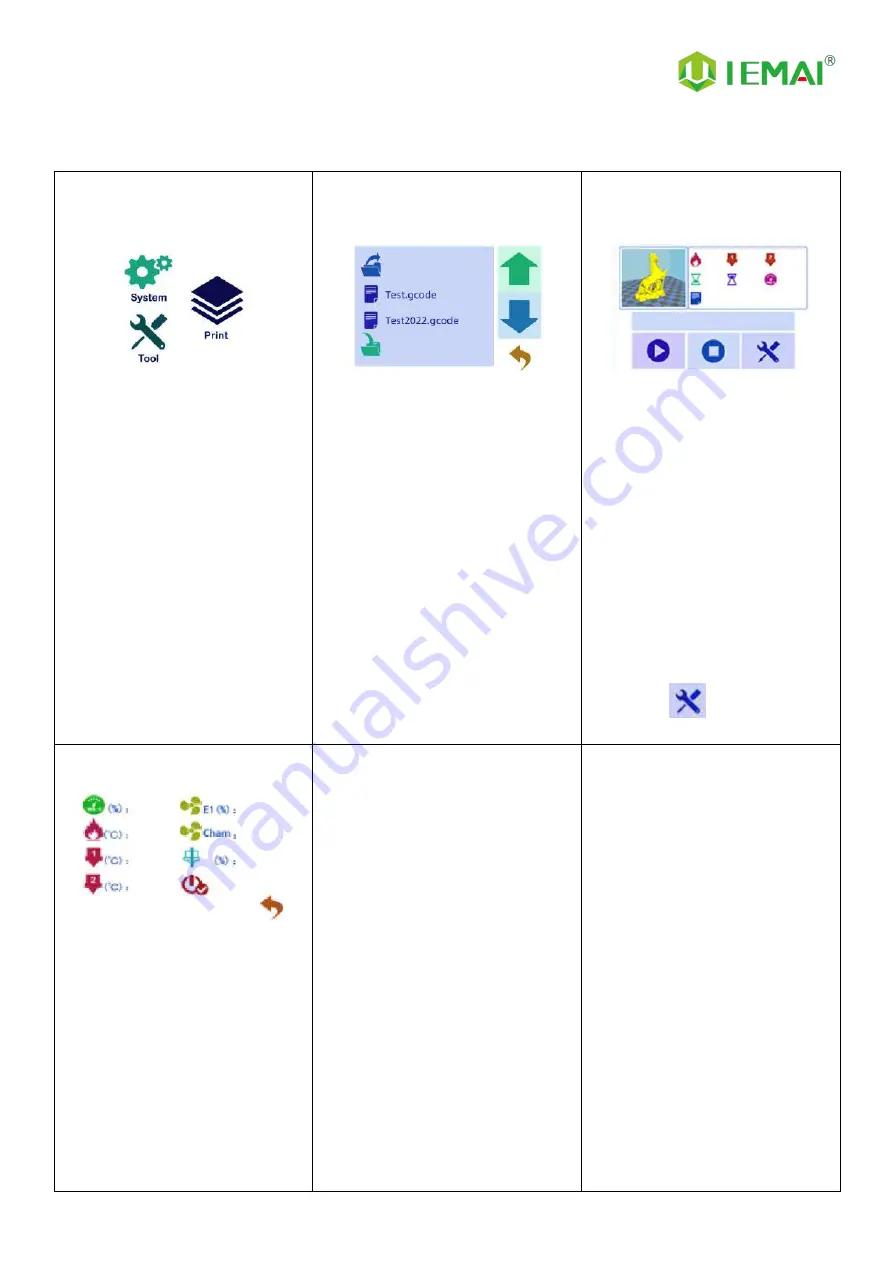
2.3.3 Print Interface

Figure 1: Main Interface

Click "Print" to go to Figure 2

Figure 2: File Interface

Check Specify G-code file to print or

delete the file

Figure 3: Print Interface

1.

This interface is the main
interface in print You can view
thumbnails

2.

Hot bed, Nozzle Temperature
and chamber temperature

3.

Elapsed time, Time remaining、
Current speed

4.

File name, Print Progress Bar,
and more

5.

You

can

control

pause

(resume) and stop printing

6.

Press "

" to reset during

the printing process

Figure 4:Print Setting Interface

1.

This interface can be adjusted
during the printing process

2.

Print Speed Ratio, Temperature
of Hot Bed, Nozzle

3.

Fan Rate of Nozzle Fan E1 and
Chamber Fan

4.

Extrusion flow

5.

As well as setting power off
after printing

Summary of Contents for MAGIC-HT-M

Page 1: ... HT M Operating Instructions www iemai3d com Please read this manual carefully before starting to operate This device is a Class A product Use in a general indoor environment may cause radio interference and therefore requires the user to take appropriate protective measures Warning ...

Page 2: ...More Materials All For Application The contents of this operating instructions may be updated periodically Scan the QR code or visit the link below to get the latest version www iemai3d com index php download ...

Page 3: ...inting Precautions 20 4 6 PC based WIFI LAN Control 21 5 Function Introduction 22 5 1 Power Failure Recovery 22 5 2 Filament Absent Warning 22 5 3 Temperature Setting of The Constant Temperature Chamber 23 6 Maintenance and Care 24 6 1 Maintenance of Linear Guide and Ball Screw 24 6 2 Adjustment of Belt Looseness 25 6 3 Dust Removal from Electrical Box Fans 26 6 4 Nozzle Maintenance 27 6 5 Print H...

Page 4: ...y with a printing temperature of up to 450 C a hot bed temperature of 150 C and a cavity temperature of 90 C It supports most polymer 3D printing materials on the market including PEEK PEKK PPSU ULTEM etc creating excellent temperature conditions to do great printing We have adopted a modular design for example both the print head and the platform can be quickly disassembled thus creating conditio...

Page 5: ...oose the high quality filament provided by other regular filament manufacturers and users should be responsible for the loss caused by using low quality filament Please keep the consumables sealed and moisture proof if not in use for a long time please bake and dry them in advance before using them again Software Please use a 64 bit system with Windows 7 or above to run the software more than 4G o...

Page 6: ...ch The maximum temperature of the printing platform of this equipment can reach 150 C its heating is strictly prohibited to touch The maximum temperature of the chamber of this equipment can reach 90 C and it is strictly forbidden to touch it when it is heated Ensure that the power supply grounding terminal is well grounded to prevent the printer from not working properly or posing a risk of elect...

Page 7: ...Print More Materials All For Application 4 2 Detailed Parameter 2 1 Specification ...

Page 8: ...Print More Materials All For Application 5 ...

Page 9: ...Print More Materials All For Application 6 2 2 Device Layout Control Panel Switch Handle Carry Machine ...

Page 10: ...Print More Materials All For Application 7 Top Window Filament Box Handle Carry Machine Motherboard Cooling Fan Cooling Fan Main Switch ...

Page 11: ...pplication 8 2 3 Interactive Interface The interactive Interface of this device adopts a 3 5 inch Color Touch Screen Resistive please read the following instructions carefully before first use Logic diagram of interactive interface ...

Page 12: ...original factory settings 5 Tap TPAAdjustment to correct the touch offset 6 Click WIFI to go to Figure 5 Figure 3 Info interface 1 This interface allows you to view the current coordinates of the XYZ axis 2 The current temperature of the left nozzle and right nozzle and hot bed Figure 4 About interface This interface allows you to view the name ID system version UI version and Power On Off sounds ...

Page 13: ...er sales contact information Figure 3 Manual Here can do the following 1 Select the moving unit of 0 1 10mm 2 Controls the XYZ axis for unit movement 3 Click to go back to the original point 4 Select E1 or E2 for unit extrusion Figure 4 Pre Heat interface 1 This interface allows you to set the preheat temperature of the hot bed left nozzle and Right nozzle Figure 5 Filament interface 1 Loading mat...

Page 14: ...mbnails 2 Hot bed Nozzle Temperature and chamber temperature 3 Elapsed time Time remaining Current speed 4 File name Print Progress Bar and more 5 You can control pause resume and stop printing 6 Press to reset during the printing process Figure 4 Print Setting Interface 1 This interface can be adjusted during the printing process 2 Print Speed Ratio Temperature of Hot Bed Nozzle 3 Fan Rate of Noz...

Page 15: ...to use tools such as knives scissors 4 Please be cautioned to avoid scratching the device Step 3 1 Check The Door Glass Whether the Control Panel is Segmentation 2 Notice the starter kit and material package are placed under the platform 3 Please connect the power to start the equipment and then move up the platform to take out Step 4 Remove the power cord from the left material box use the cutter...

Page 16: ... it moves normally as shown Step 5 1 Through pre heat via the touchscreen 2 The temperature can be set for the hot bed left nozzle and chamber 3 The temperature on the right represents the set temperature 4 The temperature on the left represents the actual temperature 5 The recommended bed temp for the first warm up 50 2 6 Nozzle temperature 210 2 7 Please be careful of high temps and handle with ...

Page 17: ...nsure that the platform does not shake Step 2 1 Raise z axis platform Step 3 1 Use fixed height objects as shown 2 Positioning platform with nozzle height Step 4 1 Adjust the nut 2 So that the platform and nozzle just pass through the object Step 5 1 Push the print head to the inner corner by hand 2 Adjust again Step 6 1 Hand push to the last corner of the adjustment after the completion of the pl...

Page 18: ...nting and Z axis compensation After testing the printing platform you can start printing If you find that the nozzle and platform spacing is not ideal during the printing process you can open and change the data in the file of Automatic leveling compensation parameters through Notepad put the changed file into the SD card and use the 3D printer to print this TXT file once the compensation paramete...

Page 19: ...rial through the break test port 2 Manually feed it to the gears Step 4 1 Click to load material 2 E1 for the nozzle Step 5 1 Till the nozzle appears fine filament 2 Click Stop loading command Step 6 3 When unloading materials 4 Pull material in advance by hand 5 and apply a certain amount of tension Step 7 1 Click to uninstall material 2 E1 for the nozzle Step 8 1 After the material exits the gea...

Page 20: ... used materials Super Performence PEEK 430 PEKK 430 PEI 1010 360 PEI 9085 360 PPSU 360 PPS 300 Reinforced Composites CF PEEK GF PEEK 450 CF PEKK ESD PEKK 430 GF PA CF PA 300 CF PC PC FR PC ABS 270 CF ABS 260 ESD PETG 260 CF PLA 220 General engineering materials PA 260 PC 260 ABS 240 PETG 230 PLA 200 TPU 230 ...

Page 21: ...he IEMAI slicing software 2 Save the code to the SD card 3 Please refer to the software tutorial for detailed slicing methods Step 2 1 Insert the SD card into the card slot on the right side of the device and select the file to be printed Step 3 1 Click ready to start printing ...

Page 22: ...ght corner of the model to insert between the model and the build platform to separate the model from the build platform Step 4 1 For the completed model the base raft needs to be removed using the correct slicing parameters the model and raft body can be easily separated as a whole by hand Step 5 1 The finished model and the separated raft are finally obtained Attention For large models that are ...

Page 23: ...high temperature head printing 2 Pre heat before printing should first heat the thermostat chamber and hot bed the print head should not be heated for a long time long time heating is easy to form carbonization lead to print head clogging clogging treatment see common problems and their solutions PEEK printing 3 Before printing the material should first use 120 baking 5H 4 printing when the coolin...

Page 24: ...y the generated file to the SD card 2 and put it on the machine to print once Step 4 1 Copy the generated file to the SD card 2 and put it on the machine to print once 3 0 0 0 0 means not connected successfully Step 5 1 Enter the software and click Scan 2 Automatically reads machines in the network and connects them Step 6 1 Green status indicates successful connection Step 7 1 Preheat and movemen...

Page 25: ...of the printer has not moved after power failure otherwise it will not be able to continue printing after the last breakpoint 5 2 Filament Absent Warning Step 1 1 If the printer runs out of material during printing 2 Please select Yes in this screen to change the material Step 2 1 Unloading materials 2 Loading materials 3 E1 for the left nozzle E2 for the right nozzle 4 Unload the existing materia...

Page 26: ... Setting of The Constant Temperature Chamber 1 Enter the fan control interface and control the chamber fan to 100 2 Enter the preheat interface to set the temperature the highest set to 90 C 5 C Attention Be sure to turn on the fan before heating up the chamber ...

Page 27: ...to avoid machine failure 6 1 Maintenance of Linear Guide and Ball Screw Ball screw and linear guide are the guarantee to keep secure operation and the correct maintenance can effectively increase the service life of the machine First step Use a towel or rag to remove the original lubricant from the linear guides and ball screws Second step Add grease apply the right amount of grease in the V groov...

Page 28: ...d every six months Step 1 Open the top cover as shown on the top 14 screws and 3 screws on both sides to remove and take off the top cover Step 2 Check the belt tightness finger lightly press the belt belt deformation of more than 2mm almost and the lower belt contact when the belt needs to be tensioned Step 3 Loosen the two screws holding down the belt tighten the screws after pulling the belt ti...

Page 29: ...nt of the motherboard and prevent the drive from overheating and out of step phenomenon Step two Removing the dust cover Insert the four corners of the dust cover from the dust cover to gently key out the dust cover Step Three Clear the dust on the dust cover and fan Use the air gun to remove the dust on the sponge inside the dust cover and blow clean the dust on the fan blow the fan pay attention...

Page 30: ...int item impact so need to be cleaned Step 1 Heat up the nozzle the last printing temperature shall prevail Step 2 Use tweezers to hold a soft fiber cloth or some other high temperature resistant soft goods wipe clean prohibit the use of sandpaper blades and other sharp with corrosive tools items grinding cleaning Note the nozzle high temperature operation attention to burns ...

Page 31: ...tion Step 4 take out the new nozzle using raw material tape clockwise around the threaded part of the nozzle 7 turns and press out the threads Step 5 Use duckbill pliers and a socket to reattach the nozzle to the print head Nozzle replacement requires timely re adjustment of the nozzle and print platform pitch for details please refer to the print install the print platform and leveling peek block...

Page 32: ...p 2 Turn off the power and loosen the three screws as shown in the figure Step 3 Pull out the print head press the pneumatic interface black rubber to pull out the feed tube complete the removal To replace the print head proceed as follows Step 1 Install the print head in the original position tighten the front two screws so that the print head is closely connected to the base and then tighten the...

Page 33: ...Print More Materials All For Application 30 6 6 Steps to Disassemble The Nozzle Step 1 Unscrew the 2 screws as shown Step 2 Loosen the top spring screw Step 3 Removal of heating block completed ...

Page 34: ...tion Problem 1 When extruding the extrusion gear shake Increase the print head temperature or determine if the head is clogged or needs to be reloaded with material Problem 2 One or two of the X Y Z and E axes cannot be moved and an alarm sound appears when you click to move Check if the limit switch is pressed Problem 3 Opposite direction of motion Open the firmware and change the control code 1 ...

Page 35: ...isplay 1023 Print head is not properly installed 7 3 Print Problem Solution Problem 1 Prompt 1 extruder no material cannot print properly Add filament at the break detection Problem 2 The print appears to be detached from the bottom and is carried away After determining that the platform is able to print that material adjust the platform and nozzle gap when the zero point is small see Printing Ins...

Page 36: ...ts caused by the material expansion of stuck filaments 2 After printing for a period of time to squeeze out some black material and not in the silk Treatment I Use the nozzle corresponding size of the needle to unclog the nozzle and extrude again will be internal Treatment II Step 1 Refer to the print head disassembly and maintenance after removing the print head Step 2 Use a 2mm drill bit to dril...

Page 37: ...ation 34 8 Appendix Appendix A The difference between high and low temperature of the print head External distinction can be seen nozzle style large square nut style for high temperature nozzle cone type for the common temperature nozzle ...

Page 38: ...g time when the residual glue on the platform is too much you can take off the carbon fiber board and rinse it with clean water and re glue it Attention It is recommended to use the side skirt attachment type for printing model with carbon fiber board to avoid the model printing warpage and other bad flat production When printing the model it is recommended to observe the printing situation well b...

Page 39: ...ance between the nozzle and the platform is more appropriate and such a skirt effectively increases the contact surface between the model and the platform increasing the adhesion force Attention If the nozzle is too close to the platform there is no gap between the platform and the nozzle it will lead to nozzle extrusion without supplies so printing with a good observation of the skirt can be very...

Reviews: