


WAFER-PV-D5252/D4252/N4552 SBC
Page 53
Step 1:
Locate the power cable
. The power cable is shown in the packing list in
Chapter 3
.
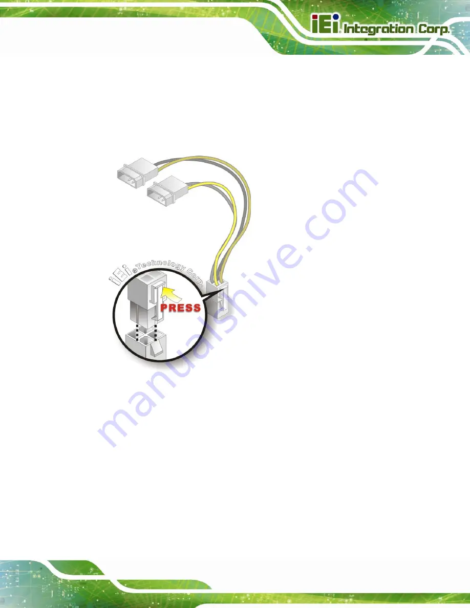
Step 2:
Connect the Power Cable to the Motherboard
. Connect the 4-pin (2x2) Molex
type power cable connector to the AT power connector on the motherboard. See
Figure 4-10: Power Cable to Motherboard Connection
Step 3:
Connect Power Cable to Power Supply
. Connect one of the 4-pin (1x4) Molex
type power cable connectors to an AT power supply. See Figure 4-12.
4.7.2 Audio Kit Installation
The Audio Kit that came with the WAFER-PV-D5252/D4252/N4552 connects to the audio
connector on the WAFER-PV-D5252/D4252/N4552. The audio kit consists of three audio
jacks. Mic-in connects to a microphone. Line-in provides a stereo line-level input to
connect to the output of an audio device. Line-out, a stereo line-level output, connects to
two amplified speakers. To install the audio kit, please refer to the steps below:
Summary of Contents for WAFER-PV-N4552
Page 13: ...WAFER PV D5252 D4252 N4552 SBC Page 1 Chapter 1 1 Introduction...
Page 17: ...WAFER PV D5252 D4252 N4552 SBC Page 5 Figure 1 4 Dimensions with Heatsink mm...
Page 21: ...WAFER PV D5252 D4252 N4552 SBC Page 9 Chapter 2 2 Packing List...
Page 25: ...WAFER PV D5252 D4252 N4552 SBC Page 13 Chapter 3 3 Connector Pinouts...
Page 52: ...WAFER PV D5252 D4252 N4552 SBC Page 40 Chapter 4 4 Installation...
Page 72: ...WAFER PV D5252 D4252 N4552 SBC Page 60 Chapter 5 5 BIOS...
Page 103: ...WAFER PV D5252 D4252 N4552 SBC Page 91 Appendix A A BIOS Options...
Page 106: ...WAFER PV D5252 D4252 N4552 SBC Page 94 Appendix B B Terminology...
Page 110: ...WAFER PV D5252 D4252 N4552 SBC Page 98 Appendix C C Digital I O Interface...
Page 113: ...WAFER PV D5252 D4252 N4552 SBC Page 101 Appendix D D Hazardous Materials Disclosure...


