


WAFER-EHL SBC
Page 60
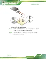
Step 3:
Connect power cable to power supply
. Connect one of the 4-pin (1x4) Molex
type power cable connectors to an AT power supply. See
Figure 4-18: Connect Power Cable to Power Supply
4.6.2
7.1 Channel Audio Kit Installation
NOTE:
This item must be ordered separately, and connects to the audio
connector. For further information please contact the nearest distributor,
reseller or vendor or contact an IEI sales representative directly.
The audio kit attaches to the audio connector. The audio kit provides 7.1 channel audio.
To install the audio kit, please refer to the steps below:
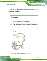
Step 1:
Connect the cable to the audio kit.
Connect the included cable to the audio
kit. Make sure pin 1 aligns with the marked pin.
Step 2:
Conect the cable to the board
. Connect the other end of the cable to the
board. Make sure to line up the marked pin 1.
Summary of Contents for WAFER-EHL Series
Page 13: ...WAFER EHL SBC Page 1 Chapter 1 1 Introduction...
Page 20: ...WAFER EHL SBC Page 8 Chapter 2 2 Unpacking...
Page 24: ...WAFER EHL SBC Page 12 Chapter 3 3 Connectors...
Page 60: ...WAFER EHL SBC Page 48 Chapter 4 4 Installation...
Page 77: ...WAFER EHL SBC Page 65 Chapter 5 5 BIOS...
Page 87: ...WAFER EHL SBC Page 75 BIOS Menu 5 CPU Configuration 2 3...
Page 98: ...WAFER EHL SBC Page 86 o Fan1 Speed Voltages o CPU_CORE o 12V o DDR o 5VSB o 3 3VSB...
Page 128: ...WAFER EHL SBC Page 116 Appendix A A Regulatory Compliance...
Page 130: ...WAFER EHL SBC Page 118 B Product Disposal Appendix B...
Page 132: ...WAFER EHL SBC Page 120 Appendix C C BIOS Options...
Page 135: ...WAFER EHL SBC Page 123 Appendix D D Watchdog Timer...
Page 138: ...WAFER EHL SBC Page 126 Appendix E E Error Beep Code...
Page 140: ...WAFER EHL SBC Page 128 Appendix F F Hazardous Materials Disclosure...