


PPC-FxxC-Q370
Page 32
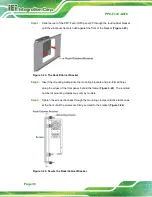
Step 4:
Align the expansion card to a PCIe slot. Press down gently, but firmly, to seat the
expansion card correctly in the slot.
Step 5:
Install the bracket screw to secure the expansion card to the system chassis.
Figure 3-15: Install and Secure Expansion Card
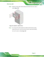
Step 6:
Re-install the rear cover and secure it with the six retention screws previously
removed.
3.9 Mounting the System
The following sections describe the mounting methods supported by the PPC-FxxC-Q370.
3.9.1 Panel Mounting
To mount the PPC-FxxC-Q370 panel PC into a panel, please follow the steps below.
Step 1:
Select the position on the panel to mount the PPC-FxxC-Q370.
Step 2:
Cut out a section of the panel that corresponds to the rear panel dimensions of
the PPC-FxxC-Q370. The recommended cutout sizes are shown below.
Summary of Contents for PPC-F C-Q370 Series
Page 17: ...PPC FxxC Q370 Page xvii BIOS Menu 31 Save Exit 87 ...
Page 18: ......
Page 19: ...PPC FxxC Q370 Page 1 Chapter 1 1 Introduction ...
Page 35: ...PPC FxxC Q370 Page 17 Chapter 2 2 Unpacking ...
Page 38: ...PPC FxxC Q370 Page 20 Chapter 3 3 Installation ...
Page 63: ...PPC FxxC Q370 Page 45 Chapter 4 4 BIOS ...
Page 106: ...PPC FxxC Q370 Page 88 Chapter 5 5 Troubleshooting and Maintenance ...
Page 110: ...PPC FxxC Q370 Page 92 6 Interface Connectors Chapter 6 ...
Page 125: ...PPC FxxC Q370 Page 107 Appendix A A Regulatory Compliance ...
Page 130: ...PPC FxxC Q370 Page 112 B Safety Precautions Appendix B ...
Page 136: ...PPC FxxC Q370 Page 118 Appendix C C BIOS Menu Options ...
Page 139: ...PPC FxxC Q370 Page 121 Appendix D D Watchdog Timer ...
Page 142: ...PPC FxxC Q370 Page 124 Appendix E E Error Beep Code ...
Page 144: ...PPC FxxC Q370 Page 126 Appendix F F Hazardous Materials Disclosure ...