


PICOe-HM650 Half-size PCIe CPU Card
Page 11
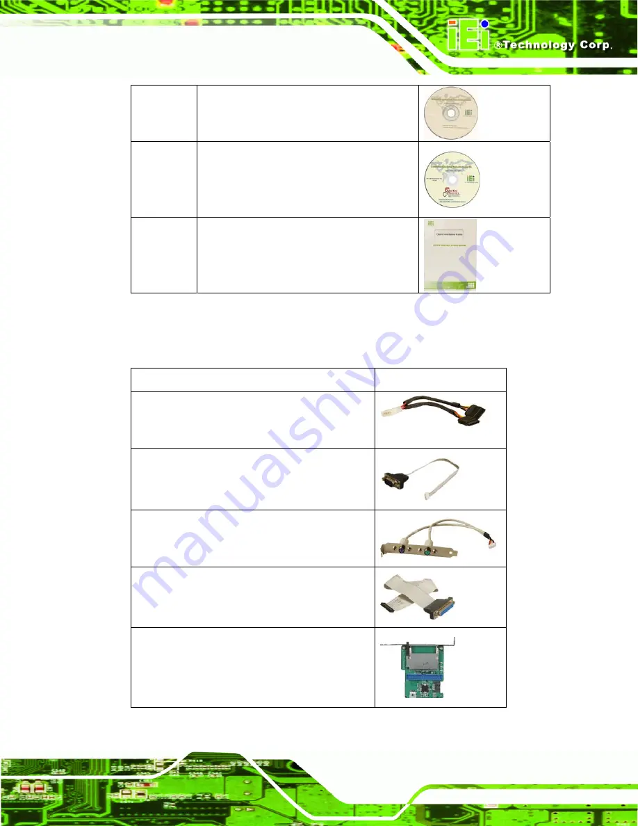
1 Utility
CD
1
One Key Recovery CD
1
Quick Installation Guide
2.3.2 Optional Items
The PICOe-HM650 is shipped with the following components:
Item and Part Number
Image
SATA power cable
(
P/N
: 32102-000100-200-RS)
RS-422/485 cable, 200 mm
(
P/N
: 32200-074800-RS)
KB/MS cable (with bracket)
(
P/N
: 19800-000075-RS)
LPT cable (wo bracket)
(
P/N
: 32200-015100-RS)
SATA to IDE/CompactFlash® converter board
(P/N: SAIDE-KIT01-R10)
Summary of Contents for PICOe-HM650
Page 15: ...PICOe HM650 Half size PCIe CPU Card Page 1 Chapter 1 1 Introduction ...
Page 22: ...PICOe HM650 Half size PCIe CPU Card Page 8 Chapter 2 2 Unpacking ...
Page 27: ...PICOe HM650 Half size PCIe CPU Card Page 13 Chapter 3 3 Connectors ...
Page 58: ...PICOe HM650 Half size PCIe CPU Card Page 44 Chapter 4 4 Installation ...
Page 85: ...PICOe HM650 Half size PCIe CPU Card Page 71 Chapter 5 5 BIOS Screens ...
Page 116: ...PICOe HM650 Half size PCIe CPU Card Page 102 Appendix A A BIOS Options ...
Page 119: ...PICOe HM650 Half size PCIe CPU Card Page 105 Appendix B B One Key Recovery ...
Page 127: ...PICOe HM650 Half size PCIe CPU Card Page 113 Figure B 5 Partition Creation Commands ...
Page 161: ...PICOe HM650 Half size PCIe CPU Card Page 147 Appendix C C Terminology ...
Page 165: ...PICOe HM650 Half size PCIe CPU Card Page 151 Appendix D D Digital I O Interface ...
Page 168: ...PICOe HM650 Half size PCIe CPU Card Page 154 Appendix E E Watchdog Timer ...
Page 171: ...PICOe HM650 Half size PCIe CPU Card Page 157 Appendix F F Hazardous Materials Disclosure ...


