background image

NAS-4300S NETWORK ATTACHED STORAGE SERVICE MANUAL


5.


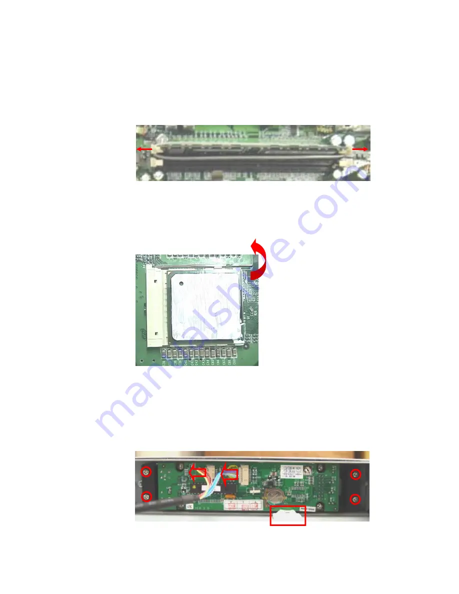
Take out the CPU and SDRAM: 

a.


SDRAM: 

Cut cable ties on SDRAM, open the side latches and remove SDRAM. 


b.


CPU: 

Pull the holders outwards then up as shown below and you can now 

remove the CPU. 


6.


Detach the LCD module assembly: 

a.


Cut the cable marked with rectangular frame in the picture below. Take 

out the cables. Then remove the screws and the LCD. 


IEI CONFIDENTIAL 

14

Summary of Contents for NAS-4300S

Page 1: ...confidence not to reproduce copy reveal or publish it in part or whole in any form 2 IEI has made reasonable effort to ensure the accuracy and validity of this document however IEI specifically discl...

Page 2: ...OVERVIEW 10 SYSTEM DISASSEMBLY AND REASSEMBLY 11 CHAPTER 5 SPARE PARTS 19 OVERVIEW 19 CHAPTER 6 PACKING FOR SHIPMENT 20 GENERAL INSTRUCTIONS 20 PACKING IN THE ORIGINAL CARTON 20 PACKING IN A DIFFERENT...

Page 3: ...lease read this user manual carefully for thorough understanding on its functions Resources Support IEI is a systems company dedicated to providing innovative products and first rate services to all o...

Page 4: ...iew The NAS 4300S requires no routine service Cleaning Caution DO NOT immerse NAS 4300S in liquid or use caustic or abrasive cleaners To clean NAS 4300S dampen a soft cloth with any commercial nonabra...

Page 5: ...troubleshooting guide is also provided it lists possible problems along with probable causes and recommended actions on how to correct each problem Who Should Perform Repairs Only qualified service pe...

Page 6: ...Services Department provides technical assistance information and replacement parts To obtain replacement parts contact the IEI Customer Services Department or your sales representative Please refer t...

Page 7: ...CD module Hard Disk Drive Tray Symptom Corrective Action The hard drive makes strange sounds when working Replace the hard disk that makes strange sound LCD module shows below error message disk drive...

Page 8: ...date and time Connect the console cables refer to Appendix B to investigate the system booting process If the system does not report any hardware failure and hangs up after booting as below figure rei...

Page 9: ...he system booting process If the system reports any hardware failure replace the main board After reinstalling the firmware the system still not works well Replace the main board Cannot connect to the...

Page 10: ...ic cover The top cover The case fan The CPU cooler The power supply The drive tray The hard disk Tools Required The tools you will need to disassemble or reassemble the NAS 4300S is listed as below On...

Page 11: ...4300S reassemble it in reverse order It is recommended that you follow this disassembly procedure in the order presented Note Before you begin to disassemble the NAS 4300S make sure that the system ha...

Page 12: ...osed in the accessory pack b Use the keys to unlock the drive tray and pull out the hard disk c Remove hard disk from the drive tray Unfasten the four screws on the back of the drive tray Then plug ou...

Page 13: ...ch the redundant power supplies Loosen the screws and use the handles to pull out the power supplies 4 Detach the CPU cooler Cut the cables with diagonal pliers Remove the fan connectors Then pull the...

Page 14: ...SDRAM open the side latches and remove SDRAM b CPU Pull the holders outwards then up as shown below and you can now remove the CPU 6 Detach the LCD module assembly a Cut the cable marked with rectangu...

Page 15: ...STORAGE SERVICE MANUAL b Loosen the LCD screws Remove LCD and the panel 7 Remove backplane a Loosen all the screws Take out the drive tray Unfasten the screws on the backplane and then remove the bac...

Page 16: ...he main board a Disconnect flat cables and all other signal cables from the main board Unfasten ten screws on main board to take off main board from drive tray Please make sure that hard disk s and po...

Page 17: ...etach the SCSI and serial connectors a Unscrew the two screws found on SCSI COM port and remove the flat cables 10 Detach the chassis side fans a Remove fan connectors Loosen the screws in anti clockw...

Page 18: ...NETWORK ATTACHED STORAGE SERVICE MANUAL 11 Detach the Ethernet switch board Remove the connector as indicated by the rectangular frames Loosen the screws and detach the Ethernet switch board IEI CONFI...

Page 19: ...CPU and the SDRAM 003ISS109 00 011 NAS 4300S Backplane 131A184 00 011 Ethernet Switch Board 131A185 00 010 LCD Module Assembly including the plastic cover 193NAS4300 000 Top Cover 41008 019539 00 Case...

Page 20: ...ve for a Returned Material Authorization RMA number Mark the shipping carton and any shipping forms with the RMA number Caution Observe ESD electrostatic discharge precautions when packing any NAS 430...

Page 21: ...NAS 4300S NETWORK ATTACHED STORAGE SERVICE MANUAL 5 Seal the carton with packing tape 6 Label carton with shipping address return address and RMA number IEI CONFIDENTIAL 21...

Page 22: ...Module DOM just replace the existing DOM with a new one containing the right version of firmware To obtain the replacement DOM please contact IEI Customer Support Department or your sales representat...

Page 23: ...CD ROM drive with the IDE cable ready on hand To reinstall the firmware on the NAS 4300S please connect the console cables to the NAS 4300S main board refer to the Appendix B 1 Turn off the power and...

Page 24: ...cable to connect the main board CN26 and the monitor Use the keyboard cable to connect the main board CN32 and the keyboard 4 Turn on the power After booting press the DELETE key to enter the BIOS se...

Page 25: ...mware Recovery CD into the fore the menu is 7 Use UP or DOWN key to select the right firmware model and version to install CD ROM drive Select Save Settings and Exit to reboot After system restarts th...

Page 26: ...on the screen 9 Hold the power button until the system is turned off Then turn on the system again and change the BIOS settings back to the factory default by choosing Auto Configuration with Optimal...

Page 27: ...e the system har driv For a list of verified hard drive models please refer to Appendix A Hard Drive Compatibility List We strongly recommend customers to use only the tested d drive models IEI cannot...

Page 28: ...f IDE hard disk drives each hard drives model might have slightly different physical dimensions For some models it may not be possible to fasten the hard disk to the drive tray with all the four screw...

Page 29: ...lume Clear Event Logs Remove all the event records Before performing the factory default setup start the browser and open the Create Disk Volume Create Network Share Create a default public share fold...

Page 30: ...S NETWORK ATTACHED STORAGE SERVICE MANUAL 2 add all the disk drives into this disk volume 3 Click OK to create the RAID volume Please wait for a while until the volume is created Select to IEI CONFIDE...

Page 31: ...share public open the browser and connect to the net Entering system administration web page and foll 1 Management and select Create to add a share he new share name and click OK to proceed work attac...

Page 32: ...AL 3 Select the option to grant all guests full access and then click Close Clear Event Logs In system administration web page go to Statistics Logs and select Event ogs Then click Clear button to cle...

Page 33: ...unexpected errors during hot swapping Table 2 NAS 4300S Hard Drive Compatibility List e s rongly recommend customers to use only these tested hard disk models Manufacturer Model Capacity IBM DTLA 305...

Page 34: ...to connect the monitor and keyboard via the console cables The console cables are included in the NAS 4300S Service Kits which can be ordered as a spare part Note Refer to Chapter 6 Spare Parts for or...

Reviews: