background image


NANO-8522 EPIC Board

Page 188 


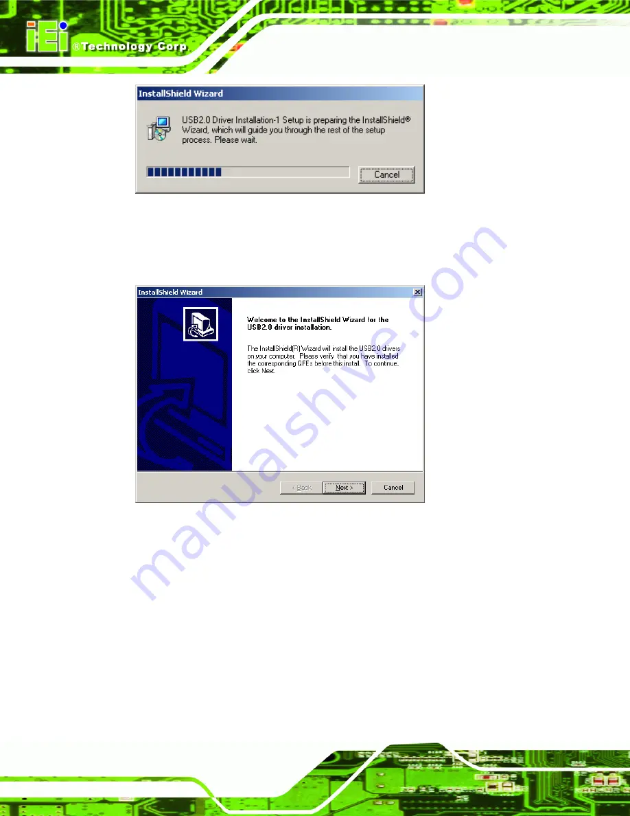
Figure 8-38: USB 2.0 InstallShield Wizard Continues 

Step 8: 

Once initialized, the 

InstallShield Wizard

 welcome screen appears 

(Figure 8-39). 


Figure 8-39: USB 2.0 InstallShield Wizard Welcome Screen 

Step 9: 

Click 

N

EXT 

to continue the installation. 

Step 10: 

The license agreement in Figure 8-40 appears. 

Summary of Contents for NANO-8522

Page 1: ...NANO 8522 EPIC Board Page i ...

Page 2: ...TA chipset changed from Ali to VIA February 2008 1 20 Updated version number to match engineering revision number October 2007 1 10 Update manual format Northbridge heatsink changed to clip free model Northbridge heatsink attachment holes removed June 2006 1 00 Initial release ...

Page 3: ...s arising out of the use or inability to use the product or documentation even if advised of the possibility of such damages This document contains proprietary information protected by copyright All rights are reserved No part of this manual may be reproduced by any mechanical electronic or other means in any form without prior written permission of the manufacturer TRADEMARKS All registered trade...

Page 4: ...e Failure to adhere to warning messages may result in permanent damage to the NANO 8522 or personal injury to the user Please take warning messages seriously CAUTION Cautionary messages should also be heeded to help reduce the chance of losing data or damaging the NANO 8522 Cautions are easy to recognize The word caution is written as CAUTION both capitalized and bold and is followed The text is t...

Page 5: ...ontained therein can help avoid making mistakes Notes are easy to recognize The word note is written as NOTE both capitalized and bold and is followed by text The text is the cautionary message A note message is shown below NOTE This is an example of a note message Notes should always be read Notes contain critical information about the NANO 8522 Please take note messages seriously ...

Page 6: ...es representative directly To contact an IEI sales representative please send an email to sales iei com tw The items listed below should all be included in the NANO 8522 package 1 x NANO 8522 single board computer 1 x Audio cable 1 x IDE cable 1 x KB MS Y cable 1 x Power cable 2 x RS 232 cable 2 x SATA cable 1 x SATA power cable 1 x Mini jumper pack 1 x Utility CD 1 x Quick installation guide QIG ...

Page 7: ...ATA FLOW 11 2 4 COMPATIBLE PROCESSORS 12 2 4 1 CPU Overview 12 2 4 2 Supported Intel Pentium M Processors 12 2 4 3 Supported Intel Celeron M Processors 13 2 5 INTEL 852GM GRAPHICS MEMORY CONTROLLER HUB 13 2 5 1 Intel 852GM Memory Support 14 2 5 2 Intel 852GM Display and Graphics Support 15 2 5 2 1 Analog CRT 15 2 5 2 2 LVDS Display Support 16 2 5 2 3 Intel 852GM Internal Graphics Controller 16 2 6...

Page 8: ...ntel 82541PI PCI Gigabit Ethernet Controller 31 2 8 3 VIA VT6421 SATA Drive Controller 32 2 8 4 PCI 104 Expansion Port 33 2 9 ENVIRONMENTAL AND POWER SPECIFICATIONS 33 2 9 1 System Monitoring 33 2 9 2 Operating Temperature and Temperature Control 34 2 9 3 Power Consumption 34 2 10 EMBEDDED SYSTEMS 34 2 10 1 NANO 8522 Embedded Systems 34 3 UNPACKING 36 3 1 ANTI STATIC PRECAUTIONS 37 3 2 UNPACKING 3...

Page 9: ...e Connector 56 4 2 12 LED Connector 57 4 2 13 LVDS LCD Connector 58 4 2 14 Parallel Port Connector 60 4 2 15 PCI 104 Slot 62 4 2 16 Power Button Connector 65 4 2 17 Reset Button Connector 65 4 2 18 SATA Drive Connectors 66 4 2 19 SATA Drive Power Connector 67 4 2 20 Serial Port Connector COM2 RS 232 RS 422 or RS 485 68 4 2 21 Serial Port Connector COM3 COM4 69 4 2 22 USB Connector Internal 70 4 3 ...

Page 10: ...3 5 5 CHASSIS INSTALLATION 94 5 5 1 Airflow 94 5 5 2 Motherboard Installation 95 5 6 INTERNAL PERIPHERAL DEVICE CONNECTIONS 95 5 6 1 Peripheral Device Cables 95 5 6 2 Audio Kit Installation 95 5 6 3 IDE Cable Connection 96 5 6 4 LVDS LCD Installation 97 5 6 5 Single RS 232 Cable w o Bracket 99 5 6 6 SATA Drive Connection 100 5 7 EXTERNAL PERIPHERAL INTERFACE CONNECTION 102 5 7 1 PS 2 Y Cable Conne...

Page 11: ...CI PNP 131 6 5 BOOT 134 6 5 1 Boot Settings Configuration 135 6 5 2 Boot Device Priority 137 6 5 3 Removable Drives 137 6 6 SECURITY 139 6 7 CHIPSET 140 6 7 1 Northbridge Configuration 142 6 7 2 Southbridge Chipset Configuration 145 6 8 POWER 146 6 9 EXIT 149 7 RAID SETUP 151 7 1 VIA RAID UTILITY 152 7 2 ACCESSING THE RAID UTILITY 152 7 3 CREATING A RAID ARRAY 153 7 3 1 Automatic Setup 154 7 3 2 M...

Page 12: ...C DIGITAL I O INTERFACE 202 C 1 INTRODUCTION 203 C 2 DIO CONNECTOR PINOUTS 203 C 3 ASSEMBLY LANGUAGE SAMPLES 204 C 3 1 Enable the DIO Input Function 204 C 3 2 Enable the DIO Output Function 204 D WATCHDOG TIMER 205 E ADDRESS MAPPING 208 E 1 DIRECT MEMORY ACCESS DMA 209 E 2 INPUT OUTPUT IO 210 E 3 INTERRUPT REQUEST IRQ 212 E 4 MEMORY 213 F HAZARDOUS MATERIALS DISCLOSURE 214 F 1 HAZARDOUS MATERIALS ...

Page 13: ...e 2 10 Realtek ALC655 Codec 20 Figure 2 11 USB 22 Figure 2 12 Serial Port Chipset 24 Figure 2 13 BIOS Chipset 25 Figure 2 14 Super I O Chipset 26 Figure 2 15 Infrared 27 Figure 2 16 Parallel Port 28 Figure 2 17 Keyboard and Mouse 29 Figure 2 18 Intel 852GM 29 Figure 2 19 PCI Interface 30 Figure 2 20 Ethernet Controller 31 Figure 2 21 SATA Drive Controller 32 Figure 2 22 PCI 104 Expansion Port 33 F...

Page 14: ...TA Drive Connector Locations 67 Figure 4 21 SATA Power Connector 68 Figure 4 22 RS 232 422 485 Serial Port Connector Location 69 Figure 4 23 Serial Port Connector Pinout Locations 70 Figure 4 24 USB Connector Pinout Locations 71 Figure 4 25 NANO 8522 External Peripheral Connector Panel 72 Figure 4 26 PS 2 Pinout and Configuration 73 Figure 4 27 Ethernet Connector 74 Figure 4 28 COM1 Pinout Locatio...

Page 15: ...igure 5 24 Serial Device Connector 105 Figure 5 25 USB Connector 106 Figure 5 26 VGA Connector 107 Figure 7 1 RAID Utility 152 Figure 7 2 RAID Setup Main Screen 153 Figure 7 3 Create Array 153 Figure 7 4 RAID Type 154 Figure 7 5 Automatic Setup 154 Figure 7 6 Confirm Data Deletion 155 Figure 7 7 RAID Array Setup Complete 155 Figure 7 8 Select Drives 156 Figure 7 9 Select First Drive 156 Figure 7 1...

Page 16: ...Setup Icon 174 Figure 8 12 Audio Driver Install Shield Wizard Starting 175 Figure 8 13 Audio Driver Setup Preparation 175 Figure 8 14 Audio Driver Welcome Screen 176 Figure 8 15 Audio Driver Software Configuration 176 Figure 8 16 Audio Driver Digital Signal 177 Figure 8 17 Audio Driver Installation Begins 177 Figure 8 18 Audio Driver Installation Complete 178 Figure 8 19 Operating Systems 178 Figu...

Page 17: ...llShield Wizard Continues 188 Figure 8 39 USB 2 0 InstallShield Wizard Welcome Screen 188 Figure 8 40 USB 2 0 License Agreement 189 Figure 8 41 USB 2 0 Driver Installed 189 Figure 8 42 USB 2 0 Driver Installation Complete 190 Figure 8 43 Locate the Setup Program Icon 191 Figure 8 44 Preparing Setup Screen 191 Figure 8 45 Install Wizard Welcome Screen 192 Figure 8 46 Software License Agreement 192 ...

Page 18: ... Table 4 5 Audio Connector Pinouts 10 pin 47 Table 4 6 Panel Backlight Connector Pinouts 48 Table 4 7 Battery Connector Pinouts 49 Table 4 8 CF Card Socket Pinouts 51 Table 4 9 DIO Connector Pinouts 52 Table 4 10 Fan Connectors Pinouts 53 Table 4 11 Secondary IDE Connector Pinouts 55 Table 4 12 Infrared Connector Pinouts 56 Table 4 13 Keyboard Mouse Connector Pinouts 57 Table 4 14 LED Connector Pi...

Page 19: ...4 28 RS 232 Serial Port COM 1 Pinouts 75 Table 4 29 USB Connector Pinouts 75 Table 4 30 VGA Connector Pinouts 76 Table 5 1 Jumpers 89 Table 5 2 CF Card Setup Jumper Settings 89 Table 5 3 Clear CMOS Jumper Settings 91 Table 5 4 COM 2 Function Select Jumper Settings 92 Table 5 5 LVDS Voltage Selection Jumper Settings 93 Table 5 6 PCI 104 Voltage Setup Jumper Settings 93 Table 5 7 IEI Provided Cables...

Page 20: ...onfiguration 126 BIOS Menu 8 Remote Access Configuration 127 BIOS Menu 9 USB Configuration 130 BIOS Menu 10 PCI PnP Configuration 132 BIOS Menu 11 Boot 134 BIOS Menu 12 Boot Settings Configuration 135 BIOS Menu 13 Boot Device Priority Settings 137 BIOS Menu 14 Removable Drives 138 BIOS Menu 15 Security 139 BIOS Menu 16 Chipset 141 BIOS Menu 17 Northbridge Chipset Configuration 142 BIOS Menu 18 Sou...

Page 21: ...NANO 8522 EPIC Board Page 1 Chapter 1 1 Introduction ...

Page 22: ... and Ethernet support The NANO 8522 supports up to two SATA hard drives up to two IDE hard drives and six USB 2 0 devices The VIA enabled SATA drives support RAID 0 for performance and RAID 1 for data protection Onboard audio is enabled via an AC 97 audio chipset 1 1 1 NANO 8522 Features Some of the NANO 8522 features are listed below RoHS compliant Support for the following CPUs o Intel Celeron M...

Page 23: ... USB 2 0 devices supported Integrated 5 1 channel audio 1 2 NANO 8522 Overview 1 2 1 NANO 8522 Overview Photo The NANO 8522 has a wide variety of internal and external peripheral connectors The peripheral connectors are connected to devices including storage devices display devices and parallel communications devices A labeled photo of the peripheral connectors is shown in Figure 1 1 Figure 1 2 NA...

Page 24: ...g connectors on board 1 x 12 V power connector 1 x ATX power button connector 1 x ATX power connector 1 x Audio connector 1 x Backlight inverter connector 1 x Battery connector 1 x CompactFlash connector 1 x DIO connector 1 x Fan connectors 1 x IDE disk drive connector 1 x Infrared connector 1 x Keyboard Mouse connector 1 x LED connector ...

Page 25: ... panel 1 x PS 2 keyboard mouse connector 1 x Ethernet connector 1 x Serial port connector 4 x USB 2 0 connector 1 x VGA connector The NANO 8522 has the following on board jumpers Clear CMOS COM2 RS232 422 485 selection CompactFlash Master Slave selection LVDS voltage selection PCI 104 SERIRQ net to CN3 pin B1 selector 1 2 3 Technical Specifications NANO 8522 technical specifications are listed in ...

Page 26: ...SO DIMM up to 1 GB Display VGA Dual channel 24 bit LVDS BIOS AMI BIOS Audio 5 1 channel audio LAN Intel 82541PI GbE on Socket 479 models Intel 82551ER Ethernet on embedded models COM Three RS 232 serial ports One RS 232 422 485 serial port USB 2 0 Six USB 2 0 devices supported IDE One 44 pin IDE connects up to two Ultra ATA33 66 100 devices SATA Two 1 5 Gb s SATA drives supported Keyboard mouse On...

Page 27: ...nsumption 12 V 0 96 A Intel Celeron M 800 MHz with 256 MB DDR 12 V 1 99 A Intel Pentium M 1 7GHz with 512 MB DDR Temperature 0ºC 60ºC 32ºF 140ºF Humidity operating 5 95 non condensing Dimensions 165 mm x 115 mm Weight GW 1 2kg Table 1 1 Technical Specifications ...

Page 28: ...NANO 8522 EPIC Board Page 8 Chapter 2 2 Detailed Specifications ...

Page 29: ...r describes the specifications and on board features of the NANO 8522 in detail 2 2 Dimensions 2 2 1 Board Dimensions The dimensions of the board are listed below and shown in Figure 2 2 Length 165 10 mm Width 115 00 mm Figure 2 1 NANO 8522 Dimensions mm ...

Page 30: ...NANO 8522 EPIC Board Page 10 2 2 2 External Interface Panel Dimensions External peripheral interface connector panel dimensions are shown in Figure 2 3 Figure 2 2 External Interface Panel Dimensions mm ...

Page 31: ...ge 11 2 3 Data Flow Figure 2 4 shows the data flow between the two on board chipsets and other components installed on the motherboard and described in the following sections of this chapter Figure 2 3 Data Flow Block Diagram ...

Page 32: ...essors 2 4 2 Supported Intel Pentium M Processors Specifications for the compatible Intel Pentium M processors are listed in Table 2 2 CPU Speed Bus Speed Mfg Tech Cache Socket Processor No 2 1GHz 400 MHz 90nm 2 MB 479 765 2 0GHz 400 MHz 90nm 2 MB 479 755 1 8GHz 400 MHz 90nm 2 MB 479 745 1 7GHz 400 MHz 90nm 2 MB 479 735 1 6GHz 400 MHz 90nm 2 MB 479 725 1 5GHz 400 MHz 90nm 2 MB 479 715 1 5GHz 400 M...

Page 33: ... 380 1 50 GHz 400 MHz 90 nm 1 MB 479 370 1 40 GHz 400 MHz 90 nm 1 MB 479 360 1 30 GHz 400 MHz 90 nm 1 MB 479 350 1 50 GHz 400 MHz 130 nm 512 KB 479 340 1 40 GHz 400 MHz 130 nm 512 KB 479 330 1 30 GHz 400 MHz 130 nm 512 KB 479 320 1 20 GHz 400 MHz 130 nm 512 KB 479 310 Table 2 2 Supported Intel Celeron M Processors 2 5 Intel 852GM Graphics Memory Controller Hub Figure 2 5 Intel 852GM The Intel 852G...

Page 34: ...vides flexible network solutions such as 10 100 Mb s or Gigabit Ethernet with LAN manageability Dual Ultra ATA 100 controllers coupled with the Intel Application Accelerator supports faster IDE transfers to storage devices Intel Application Accelerator software provides additional performance over native ATA drivers by improving I O transfer rates and enabling faster O S load time resulting in acc...

Page 35: ...t has an integrated graphics engine that supports the following display devices Analog CRT displays 24 bit dual channel LVDS Figure 2 7 Display and Graphics Support 2 5 2 1 Analog CRT The onboard Intel 852GM GMCH has an integrated 350 MHz 24 bit RAMDAC that can directly drive a progressive scan analog monitor pixel with the following specifications ...

Page 36: ...ntegrated on the Intel 852GM Northbridge chipset The Intel Extreme Graphics 2 features are listed below Enhanced Rapid Pixel and Texel Rendering Optimized visual quality and performance from the addition of hardware to support of texel formatting bicubic filter color blending accuracy and video mixing render resulting in optimized visual quality and performance Zone Rendering 2 Technology Enhances...

Page 37: ... o Embossed DOT3 bump mapping o Multi texture o DOT3 bump mapping o Point sprites Video and Display o DirectShow DirectVA o Hardware motion compensation support for DVD playback o 4x2 overlay filter o 350 MHz DAC frequency o Maximum DVO pixel rate of up to 330MP s o Flat panel monitors and TV out support via AGP Digital Display ADD cards o 350 MHz DAC for 1800x1440 85Hz max CRT resolution or 2048x...

Page 38: ...A controller Interrupt controller and timer functions Integrated IDE controller supports Ultra ATA100 66 33 USB host interface with support for five USB ports 3 UHCI host controllers 1 EHCI high speed USB 2 0 Host controller Integrated LAN controller System Management Bus SMBus Specification Version 2 0 with additional support for I2C devices Supports Audio Codec 97 Revision 2 3 specification Low ...

Page 39: ...E HDDs Specification Ultra ATA 100 Ultra ATA 66 Ultra ATA 33 IDE devices 2 2 2 PIO Mode 0 4 0 4 0 4 PIO Max Transfer Rate 16 6 MB s 16 6 MB s 16 6 MB s DMA UDMA designation UDMA 5 UDMA 4 UDMA 2 DMA UDMA Max Transfer 100 MB s 66 MB s 33 MB s Controller Interface 5 V 5 V 5 V Table 2 3 Supported HDD Specifications 2 6 2 AC 97 Controller The NANO 8522 has an integrated Realtek ALC655 Codec The ALC655 ...

Page 40: ...specifications Front Out Surround Out MIC In and LINE In Jack Sensing 14 318 MHz 24 576 MHz PLL to eliminate crystal 12 288 MHz BITCLK input Interrupt capability Three analog line level stereo inputs with 5 bit volume control LINE_IN CD AUX High quality differential CD input Two analog line level mono inputs PCBEEP PHONE IN Two software selectable MIC inputs Dedicated Front MIC input for front pan...

Page 41: ...48 pin LQFP package EAX 1 0 2 0 compatible Direct Sound 3D compatible A3D compatible I3DL2 compatible HRTF 3D positional audio 10 band software equalizer Voice cancellation and key shifting in Karaoke mode AVRack Media Player Configuration Panel for improved user convenience 2 6 3 USB Controller The onboard Intel ICH4 supports six USB ports on the backplane USB connectors on the backplane are inte...

Page 42: ...Controller Interface UHCI controllers High speed full speed and low speed capable 2 6 4 PCI Interface The PCI interface on the ICH4 is compliant with the PCI Revision 2 2 implementation Some of the features of the PCI interface are listed below PCI Revision 2 2 compliant 33 MHz 5 V tolerant PCI signals except PME Integrated PCI arbiter supports up to six PCI bus masters ...

Page 43: ...e LPC 1 0 specifications The LPC bus from the ICH4 is connected to the following components BIOS chipset Super I O chipset 2 7 LPC Bus Components 2 7 1 LPC Bus Overview The LPC bus is connected to components listed below BIOS chipset Fintek F81216DG Serial I O chipset Winbond W83627EHG Super I O chipset ...

Page 44: ...erial port chipset is interfaced to the Southbridge chipset through the LPC bus Figure 2 12 Serial Port Chipset Some of the features of the Fintek chipset are listed below Supports LPC interface Totally provides 4 UART 16550 asynchronous ports o 3 x Pure UART o 1 x UART IR One Watch dog timer with WDTOUT signal One Frequency input 24 48 MHz Powered by 3 Vcc 2 7 3 BIOS Chipset The BIOS chipset has ...

Page 45: ... Flash BIOS SMIBIOS DMI compliant Console redirection function support PXE Pre boot Execution Environment support USB booting support The BIOS chipset is shown in Figure 2 13 below 2 7 4 Super I O chipset The Winbond W83627EHG Super I O chipset is connected to the ICH4 Southbridge through the LPC bus ...

Page 46: ...e Design Guide compliant ACPI DPM Device Power Management supported Some of the Super I O features are described in more detail below 2 7 4 1 LPC Interface The LPC interface on the Super I O complies with the Intel Low Pin Count Specification Rev 1 01 The LPC interface supports both LDRQ and SERIRQ protocols as well as PCI PME interfaces 2 7 4 2 Infrared The onboard Super I O supports the followin...

Page 47: ...tion menu 2 7 4 4 Parallel Port The Super I O parallel port LPT is compatible with the following LPT specifications IBM parallel port compatible PS 2 compatible bi directional parallel port Enhanced Parallel Port EPP mode supported Compatible with IEEE 1284 specifications Extended Parallel Port EPP mode supported Compatible with IEEE 1284 specifications Enhanced printer port back drive current pro...

Page 48: ...8042 compatible Asynchronous access to two data registers and one status register Compatible with 8042 software PS 2 mouse supported Port 92 supported Interrupt and polling modes supported Fast Gate A20 and Hardware Keyboard Reset 8 bit timer counter The keyboard and mouse controller is interfaced to a keyboard and mouse connected to the backplane through the board to board connectors ...

Page 49: ...O Ports The Super I O has a 10 pin 8 bit programmable digital input output port Figure 2 18 Intel 852GM 2 7 4 7 Fan Speed and Fan Control The super I O can monitor the fan speed The super I O is interfaced to the fan on the backplane through the board to board connectors ...

Page 50: ... embedded CPU models Intel 82541PI PCI Gigabit Ethernet controller socket 479 model VIA VT6421 SATA controller PCI 104 Expansion port The PCI bus complies with PCI Local Bus Specification Revision 2 2 supports 33 MHz PCI operations and 133 MB s maximum throughput 2 8 1 Intel 82551ER PCI Ethernet Controller The Intel 82551ER PCI Ethernet controller is shown in Figure 2 20 ...

Page 51: ...ower Interface specifications Offloads TCP UDP and IP checksums from PC processor Early receive interrupt processes receive data concurrently 3 3 V device The PCI Ethernet controller is connected to an RJ 45 connector on the NANO 8522 2 8 2 Intel 82541PI PCI Gigabit Ethernet Controller The Intel 82541PI PCI Gigabit Ethernet controller replaces the Intel 82551ER on Socket 479 models Some the featur...

Page 52: ...The PCI Ethernet controller is connected to an RJ 45 connector on the NANO 8522 2 8 3 VIA VT6421 SATA Drive Controller A VIA VT6421 SATA drive controller is connected to two SATA drive connectors and interfaced to the system through the PCI bus Figure 2 21 SATA Drive Controller The VIA VT6421 SATA drive controller has the following features SATA specification revision 1 0 compliant PCI specificati...

Page 53: ...owing features 33 MHz PCI Bus Operation 4 x 30pin 2 mm stack through connector Supports up to 4 boards in a stack Stackable with PC 104 and PC 104 boards 3 3 V or 5 V operation 2 9 Environmental and Power Specifications 2 9 1 System Monitoring Three thermal inputs on the NANO 8522 Super I O Enhanced Hardware Monitor monitors the following temperatures System temperature CPU temperature Eight volta...

Page 54: ...e heat sink before it is mounted on the CPU A heat sink is also mounted on the Northbridge chipset to ensure the operating temperature remains low 2 9 3 Power Consumption Table 2 4 shows the power consumption parameters for the NANO 8522 running with a 1 0GHz Intel Celeron M processor and with a 512 MB 333 MHz DDR DIMM Voltage Current 12 V 1 37 A Table 2 4 Power Consumption 2 10 Embedded Systems 2...

Page 55: ...l ports 1 x RS 232 422 485 port Two additional GbE ports 1 x eSATA port ECN 170BSEB Intel Pentium M 1 6GHz Celeron M 1 5GHz Line in Line out MIC in 4 ch video capture card ECN 170BSEC Intel Pentium M 1 6GHz 4 ch video capture card ECN 171BSEO Intel Pentium M 1 6GHz Celeron M 1 5GHz Two additional GbE ports 2 5 SATA HDD ECN 171BSEA Intel Pentium M 1 6GHz Celeron M 1 5GHz Two additional GbE ports 2 ...

Page 56: ...NANO 8522 EPIC Board Page 36 Chapter 3 3 Unpacking ...

Page 57: ... wristband can help to prevent ESD from damaging the board Self grounding Before handling the board touch any grounded conducting material During the time the board is handled frequently touch any conducting materials that are connected to the ground Use an anti static pad When configuring the NANO 8522 place it on an antic static pad This reduces the possibility of ESD damaging the NANO 8522 Only...

Page 58: ...sed the NANO 8522 from or contact an IEI sales representative directly To contact an IEI sales representative please send an email to sales iei com tw 3 3 1 Package Contents The NANO 8522 is shipped with the following components Quantity Item and Part Number Image 1 NANO 8522 1 HDD cable P N 32200 000009 RS 1 KB MS PS 2 Y cable P N 32000 000138 RS 1 Audio cable P N 32000 072100 RS 2 SATA cables P ...

Page 59: ... SATA power cable P N 32100 088600 RS 1 1 COM w o bracket P N 32200 000049 RS 1 AT 12 V Cable P N 32100 087100 RS 1 Mini jumper Pack P N 33100 000033 RS 1 Quick Installation Guide P N 51000 022027 RS 1 Utility CD P N IEI 7B000 000104 RS Table 3 1 Package List Contents ...

Page 60: ...NANO 8522 EPIC Board Page 40 3 3 2 Optional Components The following components are optional Item and Part Number Image CPU cooler P N CF 479B RS Table 3 2 Optional Components ...

Page 61: ...NANO 8522 EPIC Board Page 41 Chapter 4 4 Connector Pinouts ...

Page 62: ...ipheral interface connector locations Section 4 1 2 lists all the peripheral interface connectors seen in Section 4 1 1 4 1 1 NANO 8522 Layout Figure 4 5 shows the on board peripheral connectors rear panel peripheral connectors and on board jumpers Figure 4 1 Connector and Jumper Locations ...

Page 63: ...n be found below Connector Type Label AT power connector 4 pin header CN4 ATX power supply enable connector 3 pin connector CN2 Audio connector 10 pin header AUDIO1 Backlight inverter connector 5 pin wafer CN1 Battery connector 2 pin connector BT1 CompactFlash connector CF connector CN6 Digital I O connector 10 pin header DIO1 Fan connector CPU 3 pin wafer FAN1 IDE Interface connector 44 pin box h...

Page 64: ... port connector 10 pin header COM4 SATA drive connector 7 pin SATA S_ATA1 SATA drive connector 7 pin SATA S_ATA2 SATA drive power connector 2 pin box header CN7 SO DIMM connector SO DIMM connector J3 USB connector 8 pin header USB3 Table 4 1 Peripheral Interface Connectors 4 1 3 External Peripheral Interface Panel Connectors Table 4 5 lists the external peripheral interface panel connectors on the...

Page 65: ...e only accessible when the motherboard is outside of the chassis This section has complete descriptions of all the internal peripheral connectors on the NANO 8522 4 2 1 ATX Power Supply Connector CN Label CN4 CN Type 4 pin ATX power connector 2x2 CN Location See Figure 4 3 CN Pinouts See Table 4 3 The 4 pin 12 V ATX power supply connector is connected to a 12 V ATX power supply Figure 4 3 12 V ATX...

Page 66: ...4 4 The ATX power supply enable connector enables the NANO 8522 to be connected to an ATX power supply In default mode the NANO 8522 can only us an AT power supply To enable an ATX power supply the AT Power Select jumper must also be configured Please refer to Chapter 3 for more details Figure 4 4 ATX Power Supply Enable Connector Location PIN NO DESCRIPTION 1 5 VSB 2 GND 3 PSON Table 4 4 ATX Powe...

Page 67: ...dio connector is connected to external audio devices including speakers and microphones for the input and output of audio signals to and from the system Figure 4 5 Audio Connector Pinouts 10 pin PIN NO DESCRIPTION PIN NO DESCRIPTION 1 Line out R 2 Line in R 3 GND 4 GND 5 Line out L 6 Line in L 7 GND 8 GND 9 MIC in 10 NC Table 4 5 Audio Connector Pinouts 10 pin ...

Page 68: ... backlight inverter connector provides the backlight on the LCD display connected to the NANO 8522 with 12 V of power Figure 4 6 Panel Backlight Connector Pinout Locations PIN NO DESCRIPTION 1 BL_ADJ 2 GND 3 12 V 4 GND 5 BL_EN Table 4 6 Panel Backlight Connector Pinouts 4 2 5 Battery Connector CN Label BT1 CN Type 2 pin wafer 1x2 CN Location See Figure 4 7 ...

Page 69: ...ettings have been made and the system cannot boot up Figure 4 7 Battery Connector Location PIN NO DESCRIPTION 1 Battery 2 Ground Table 4 7 Battery Connector Pinouts 4 2 6 CompactFlash Socket CN Label CN6 solder side CN Type 50 pin header 2x25 CN Location See Figure 4 8 CN Pinouts See Table 4 8 A CF Type I or Type II memory card is inserted to the CF socket on the solder side of the NANO 8522 ...

Page 70: ...NANO 8522 EPIC Board Page 50 Figure 4 8 CF Card Socket Location PIN NO DESCRIPTION PIN NO DESCRIPTION 1 GROUND 26 CD1 2 SDD3 27 SDD11 3 SDD4 28 SDD12 4 SDD5 29 SDD13 ...

Page 71: ...D 40 N C 16 GROUND 41 IDERST 17 GROUND 42 SIORDY 18 SDA2 43 SDREQ 19 SDA1 44 SDDACK 20 SDA0 45 IDEACTS 21 SDD0 46 CF2 22 SDD1 47 SDD8 23 SDD2 48 SDD9 24 N C 49 SDD10 25 GROUND 50 GROUND Table 4 8 CF Card Socket Pinouts 4 2 7 Digital Input Output DIO Connector CN Label DIO1 CN Type 10 pin header 2x5 CN Location See Figure 4 9 CN Pinouts See Table 4 9 The digital input output connector is managed th...

Page 72: ...outs 4 2 8 Fan Connectors CN Label FAN1 CN Type 3 pin wafer connector CN Location See Figure 4 10 CN Pinouts See Table 4 10 The FAN1 cooling fan connector provides a 12 V current to the cooling fan The connector has a rotation pin to get rotation signals from the fan and notify the system so the system BIOS can recognize the fan speed Please note that only certain fans can issue the rotation signa...

Page 73: ...AN1 1 DET 2 VCC 3 GND Table 4 10 Fan Connectors Pinouts 4 2 9 IDE Connector 44 pin CN Label IDE1 CN Type 44 pin header 2x22 CN Location See Figure 4 11 CN Pinouts See Table 4 11 One 44 pin IDE device connector on the NANO 8522 supports connectivity to two hard disk drives ...

Page 74: ...Board Page 54 Figure 4 11 Secondary IDE Device Connector Locations PIN NO DESCRIPTION PIN NO DESCRIPTION 1 RESET 2 GROUND 3 DATA 7 4 DATA 8 5 DATA 6 6 DATA 9 7 DATA 5 8 DATA 10 9 DATA 4 10 DATA 11 11 DATA 3 12 DATA 12 ...

Page 75: ... 30 GROUND DEFAULT 31 INTERRUPT 32 N C 33 SA1 34 N C 35 SA0 36 SA2 37 HDC CS0 38 HDC CS1 39 HDD ACTIVE 40 GROUND 41 VCC 42 VCC 43 GROUND 44 N C Table 4 11 Secondary IDE Connector Pinouts 4 2 10 Infrared Interface Connector 5 pin CN Label IR1 CN Type 5 pin header 1x5 CN Location See Figure 4 12 CN Pinouts See Table 4 12 The infrared interface connector supports both Serial Infrared SIR and Amplitud...

Page 76: ...D 5 IR TX Table 4 12 Infrared Connector Pinouts 4 2 11 Keyboard Mouse Connector CN Label KBMS1 CN Type 6 pin header 1x6 CN Location See Figure 4 13 CN Pinouts See Table 4 13 The keyboard and mouse connector can be connected to a standard PS 2 cable or PS 2 Y cable to add keyboard and mouse functionality to the system ...

Page 77: ...KB CLK 6 GROUND Table 4 13 Keyboard Mouse Connector Pinouts 4 2 12 LED Connector CN Label CN5 CN Type 6 pin wafer 1x6 CN Location See Figure 4 14 CN Pinouts See Table 4 14 The LED connector connects to an HDD indicator LED and a power LED on the system chassis to inform the user about HDD activity and the power on off status of the system ...

Page 78: ...wer LED 4 Power LED 5 HDD LED 6 HDD LED Table 4 14 LED Connector Pinouts 4 2 13 LVDS LCD Connector CN Label LVDS1 CN Type 30 pin crimp 2x10 CN Location See Figure 4 15 CN Pinouts See Table 4 15 The 30 pin LVDS LCD connector can be connected to single channel or dual channel 18 bit or 36 bit LVDS panel ...

Page 79: ...or Pinout Locations PIN NO DESCRIPTION PIN NO DESCRIPTION 1 GROUND 2 GROUND 3 LVDSA_Y0 4 LVDSA_Y0 5 LVDSA_Y1 6 LVDSA_Y1 7 LVDSA_Y2 8 LVDSA_Y2 9 LVDSA_CLK 10 LVDSA_CLK 11 LVDSA_Y3 12 LVDSA_Y3 13 GROUND 14 GROUND 15 LVDSB_Y0 16 LVDSB_Y0 17 LVDSB_Y1 18 LVDSB_Y1 ...

Page 80: ...ROUND 27 VCC_LVDS 28 VCC_LVDS 29 VCC_LVDS 30 VCC_LVDS Table 4 15 LVDS LCD Port Connector Pinouts 4 2 14 Parallel Port Connector CN Label LPT1 CN Type 26 pin box header CN Location See Figure 4 16 CN Pinouts See Table 4 16 The 26 pin parallel port connector connects to a parallel port connector interface or some other parallel port device such as a printer ...

Page 81: ...ANO 8522 EPIC Board Page 61 Figure 4 16 Parallel Port Connector Location PIN DESCRIPTION PIN DESCRIPTION 1 RSTROBE 14 ALF 2 RPD0 15 ERROR 3 RPD1 16 PAR_INI 4 RPD2 17 SLCTIN 5 RPD3 18 GND1 6 RPD4 19 GND2 ...

Page 82: ...0 ACK 23 GND6 11 BUSY 24 GND7 12 PE 25 GND8 13 SLCT 26 N C Table 4 16 Parallel Port Connector Pinouts 4 2 15 PCI 104 Slot CN Label CN3 CN Type 120 pin PCI 104 slot CN Location See Figure 4 17 CN Pinouts See Table 4 17 The PCI 104 slot enables a PCI 104 compatible expansion module to be connected to the board ...

Page 83: ...NANO 8522 EPIC Board Page 63 Figure 4 17 PCI 104 Slot Location Pin No Column A Column B Column C Column D 1 GND 5V TBD1 5V AD00 2 VI O1 AD02 AD01 5V ...

Page 84: ... 12 3 3V TRDY GND DEVSEL 13 FRAME GND IRDY 3 3V 14 GND AD16 3 3V C BE2 15 AD18 3 3V AD17 GND 16 AD21 AD20 GND AD19 17 3 3V AD23 AD22 3 3V 18 IDSEL0 GND IDSEL1 IDSEL2 19 AD24 C BE3 VI O1 IDSEL3 20 GND AD26 AD25 GND 21 AD29 5V AD28 AD27 22 5V AD30 GND AD31 23 REQ0 GND REQ1 VI O2 24 GND REQ2 5V GNT0 25 GNT1 VI O3 GNT2 GND 26 5V CLK0 GND CLK1 27 CLK2 5V CLK3 GND 28 GND INTD 5V RST 29 12V INTA INTB INT...

Page 85: ...button connector is connected to a power switch on the system chassis to enable users to turn the system on and off Figure 4 18 Power Button Connector Location PIN NO DESCRIPTION 1 GND 2 Power Switch Table 4 18 Power Button Connector Pinouts 4 2 17 Reset Button Connector CN Label RST1 CN Type 2 pin wafer 1x2 CN Location See Figure 4 19 CN Pinouts See Table 4 19 ...

Page 86: ...ons PIN NO DESCRIPTION 1 Reset Switch 2 GND Table 4 19 Reset Button Connector Pinouts 4 2 18 SATA Drive Connectors CN Label SATA1 SATA2 CN Type 7 pin SATA drive connectors CN Location See Figure 4 20 CN Pinouts See Table 4 20 The SATA drive connectors are connected to SATA 1 5 Gb s disk drives that transfer data at speeds as high as 1 5 Gb s The SATA drives can be configured in a RAID 0 RAID 1 or ...

Page 87: ...ON 1 GND 2 TX 3 TX 4 GND 5 RX 6 RX 7 GND Table 4 20 SATA Drive Connector Pinouts 4 2 19 SATA Drive Power Connector CN Label CN7 CN Type 2 pin 5 V power supply CN Location See Figure 4 21 CN Pinouts See Table 4 21 This connector provides 5 V power to the SATA hard drives connected to it ...

Page 88: ... COM2 CN Type 14 pin header 2x7 CN Location See Figure 4 22 CN Pinouts See Table 4 22 The 14 pin serial port connector connects to the COM 2 serial communications channels COM 2 is a multi function channel In default mode COM 2 is an RS 232 serial communication channel but with the COM 2 function select jumper can be configured as either an RS 422 or RS 485 serial communications channel ...

Page 89: ...SCRIPTION 1 NDCD2 8 NDSR2 2 NRX2 9 NRTS2 3 NTX2 10 NCTS2 4 NDTR2 11 NRI2 5 GND 12 GND 6 TXD485 13 TXD485 7 RXD485 14 RXD485 Table 4 22 RS 232 RS 485 Serial Port Connector Pinouts 4 2 21 Serial Port Connector COM3 COM4 CN Label COM3 COM4 CN Type 10 pin header 2x5 CN Location See Figure 4 23 CN Pinouts See Table 4 23 ...

Page 90: ...ure 4 23 Serial Port Connector Pinout Locations PIN NO DESCRIPTION PIN NO DESCRIPTION 1 Data Carrier Direct DCD 2 Data Set Ready DSR 3 Receive Data RXD 4 Request To Send RTS 5 Transmit Data TXD 6 Clear To Send CTS 7 Data Terminal Ready DTR 8 Ring Indicator RI 9 Ground GND 10 Ground GND Table 4 23 Serial Connector Pinouts 4 2 22 USB Connector Internal CN Label USB3 CN Type 8 pin header 2x4 CN Locat...

Page 91: ...rts Each USB connector can support two USB devices Additional external USB ports are found on the rear panel The USB ports are used for I O bus expansion Figure 4 24 USB Connector Pinout Locations PIN DESCRIPTION PIN DESCRIPTION 1 USBV4L 2 GND 3 DATA4_N 4 DATA5_P 5 DATA4_P 6 DATA5_N 7 GND 8 USBV4L Table 4 24 USB Port Connector Pinouts ...

Page 92: ... motherboard is installed in a chassis The external peripheral connectors are 1 x Keyboard Mouse connector 1 x RJ 45 Ethernet connector 1 x Serial port 4 x USB 2 0 ports 1 x VGA connector Figure 4 25 NANO 8522 External Peripheral Connector Panel 4 3 1 Keyboard Mouse Connector CN Label KBMS1 CN Type PS 2 CN Location See Figure 4 26 CN Pinouts See Table 4 25 The NANO 8522 keyboard and mouse connecto...

Page 93: ...ble 4 25 Keyboard Connector Pinouts 4 3 2 Ethernet Connector CN Label J1 CN Type RJ 45 ports CN Location See Figure 4 27 CN Pinouts See Table 4 26 and Table 4 27 A 1 Gb connection can be made between the Ethernet connectors and a Local Area Network LAN through a network hub PIN DESCRIPTION PIN DESCRIPTION 1 TX0 7 TX3 2 TX0 8 TX3 3 TX1 9 Active ...

Page 94: ...tes activity on the port and the yellow LED indicates the port is linked Table 4 27 SPEED LED LINK LED Status Description Status Description GREEN ON 100 MB OFF 10 MB YELLOW ON Linked Flashing Activity Table 4 27 Ethernet Connector LEDs 4 3 3 Serial Port Connectors CN Label COM1 CN Type DB 9 connectors CN Location See Figure 4 25 CN Pinouts See Table 4 28 and Figure 4 28 The 9 pin DB 9 COM 1 seria...

Page 95: ...ts Figure 4 28 COM1 Pinout Locations 4 3 4 USB Connectors CN Label USB1 USB2 CN Type USB port CN Location See Figure 4 25 CN Pinouts See Table 4 29 USB devices connect directly to the USB connector on the external peripheral connector panel PIN DESCRIPTION PIN DESCRIPTION 1 VCC 5 VCC 2 USBD0 6 USBD1 3 USBD0 7 USBD1 4 GND 8 GND Table 4 29 USB Connector Pinouts ...

Page 96: ...rd HD D sub 15 female connector connects to a CRT or LCD monitor Figure 4 29 VGA Connector PIN Description PIN Description 1 RED 2 GREEN 3 BLUE 4 N C 5 GND 6 GND 7 GND 8 GND 9 VCC 10 GND 11 N C 12 DDC DAT 13 HSYNC 14 VSYNC 15 DDC CLK Table 4 30 VGA Connector Pinouts 4 4 On board Jumpers The NANO 8522 has five on board jumpers Refer to Section 5 4 for jumper configuration settings ...

Page 97: ...NANO 8522 EPIC Board Page 77 Chapter 5 5 Installation ...

Page 98: ...m damaging the board Self grounding Before handling the board touch any grounded conducting material During the time the board is handled frequently touch any conducting materials that are connected to the ground Use an anti static pad When configuring the NANO 8522 place it on an antic static pad This reduces the possibility of ESD damage Only handle the edges of the PCB When handling the PCB hol...

Page 99: ... an antistatic pad o When installing or configuring the motherboard place it on an antistatic pad This helps to prevent potential ESD damage Turn off all power to the NANO 8522 o When working with the NANO 8522 make sure that it is disconnected from all power supplies and that no electricity is being fed into the system Before and during the installation of the NANO 8522 DO NOT do the following DO...

Page 100: ...adequate ventilation The correct power supply is being used The following devices if applicable are properly connected o IDE device o SATA drives o ATX power enable o LVDS monitor o Power switch o Reset switch o Power supply o USB cable o Serial port cable o Parallel port cable o Keyboard mouse cable o Network cables The following external peripheral devices are properly connected to the chassis o...

Page 101: ...o result in injury to the user The CPU CPU cooling kit and DIMM are the most critical components of the NANO 8522 If one of these component is not installed the NANO 8522 cannot run 5 3 1 Socket 479 CPU Installation WARNING CPUs are expensive and sensitive components When installing the CPU please be careful not to damage it in anyway Make sure the CPU is installed properly and ensure the correct ...

Page 102: ...of foreign material If any debris is found remove it with compressed air Step 3 Correctly Orientate the CPU Make sure the IHS integrated heat sink side is facing upwards Step 4 Correctly position the CPU Match the Pin 1 mark with the cut edge on the CPU socket See Figure 5 1 Step 5 Align the CPU pins Carefully align the CPU pins with the holes in the CPU socket Step 6 Insert the CPU Gently insert ...

Page 103: ... Lock the CPU Socket Retention Screw 5 3 2 Socket 479 Cooling Kit Installation Figure 5 3 IEI Cooling Kits The IEI Socket 479 CPU cooling kit Figure 5 3 can be purchased separately The cooling kit comprises a CPU heat sink and a cooling fan ...

Page 104: ...llow the steps below Step 1 Align the support bracket Remove the tape from the support bracket From the solder side of the PCB align the support bracket to the holes on the PCB Figure 5 4 Cooling Kit Support Bracket Step 2 Place the cooling kit onto the CPU Make sure the CPU cooling fan cable can be properly routed when the cooling kit is installed Step 3 Properly align the cooling kit Make sure i...

Page 105: ...ach nut a few turns at a time and do not over tighten the screws Over tightening can cause damage to the CPU Step 5 Connect the fan cable Connect the cooling kit fan cable to the fan connector on the motherboard Carefully route the cable and avoid heat generating chips and fan blades See Figure 5 6 Step 0 Figure 5 6 Connect the cooling fan cable ...

Page 106: ...eps below and refer to Figure 5 7 Figure 5 7 SO DIMM Installation Step 1 Locate the SO DIMM socket Place the NANO 8522 on an anti static pad with the solder side facing up Step 2 Align the SO DIMM with the socket The SO DIMM must be oriented in such a way that the notch in the middle of the SO DIMM must be aligned with the plastic bridge in the socket Step 3 Insert the SO DIMM Push the SO DIMM chi...

Page 107: ...upported CF cards please refer to Chapter 2 To install the a CF card Type 1 or Type 2 onto the NANO 8522 please follow the steps below Step 1 Locate the CF card socket Place the NANO 8522 on an anti static pad with the solder side facing up Locate the CF card Step 2 Align the CF card Make sure the CF card is properly aligned with the CF socket Step 3 Insert the CF card Gently insert the CF card in...

Page 108: ...ctrical circuit It consists of two or three metal pins and a small metal clip often protected by a plastic cover that slides over the pins to connect them To CLOSE SHORT a jumper means connecting the pins of the jumper with the plastic clip and to OPEN a jumper means removing the plastic clip from a jumper Figure 5 9 Jumper Locations ...

Page 109: ...ector JP6 3 pin header PCI 104 Serial IRQ selector JP5 2 pin header Table 5 1 Jumpers 5 4 1 CF Card Setup Jumper Label JP1 Jumper Type 2 pin header Jumper Settings See Table 5 2 Jumper Location See Figure 5 10 The CF Card Setup jumper sets the CF Type I card or CF Type II cards as either the slave device or the master device CF Card Setup jumper settings are shown in Table 5 2 CF Card Setup Descri...

Page 110: ...m BIOS information To do this use the jumper cap to close pins 2 and 3 for a few seconds then reinstall the jumper clip back to pins 1 and 2 If the CMOS Settings Wrong message is displayed during the boot up process the fault may be corrected by pressing the F1 to enter the CMOS Setup menu Do one of the following Enter the correct CMOS setting Load Optimal Defaults Load Failsafe Defaults After hav...

Page 111: ... Clear CMOS Jumper 5 4 3 COM 2 Function Select Jumper Jumper Label JP2 Jumper Type 6 pin header Jumper Settings See Table 5 4 Jumper Location See Figure 5 12 The COM 2 Function Select jumper sets the communication protocol used by the second serial communications port COM 2 as RS 232 RS 422 or RS 485 The COM 2 Function Select settings are shown in Table 5 4 COM 2 Function Select Description Short ...

Page 112: ...tage Selection WARNING Permanent damage to the screen and NANO 8522 may occur if the wrong voltage is selected with this jumper Please refer to the user guide that cam with the monitor to select the correct voltage Jumper Label JP6 Jumper Type 3 pin header Jumper Settings See Table 5 5 Jumper Location See Figure 5 13 The LVDS Voltage Selection jumper allows the LVDS screen voltage to be set The LV...

Page 113: ...ons 5 4 5 PCI 104 Serial IRQ Selector Jumper Label JP5 Jumper Type 2 pin header Jumper Settings See Table 5 5 Jumper Location See Figure 5 13 The PCI 104 Serial IRQ Selector enables the serial IRQ protocol for this device The PCI 104 Serial IRQ Selector jumper settings are shown in Table 5 5 PCI 104 B1 selector Description Open Disconnect Default Closed Connect Table 5 6 PCI 104 Voltage Setup Jump...

Page 114: ...e out The NANO 8522 must be installed in a chassis with ventilation holes on the sides allowing airflow to travel through the heat sink surface In a system with an individual power supply unit the cooling fan of a power supply can also help generate airflow through the board surface NOTE IEI has a wide range of backplanes available Please contact your NANO 8522 vendor reseller or an IEI sales repr...

Page 115: ...5 7 IEI Provided Cables 5 6 2 Audio Kit Installation The Audio Kit that came with the NANO 8522 connects to the 10 pin audio connector on the NANO 8522 The audio kit consists of three audio jacks One audio jack Mic In connects to a microphone The remaining two audio jacks Line In and Line Out connect to two speakers To install the audio kit please refer to the steps below Step 1 Locate the audio c...

Page 116: ...ble Connection The IDE cable connects to the NANO 8522 to one or two IDE devices To connect an IDE HDD to the NANO 8522 please follow the instructions below Step 1 Locate the IDE connector The location s of the IDE device connector s is are shown in Chapter 3 Step 2 Insert the connector Connect the IDE cable connector to the onboard connector See Figure 5 16 A key on the front of the cable connect...

Page 117: ... LCD Installation The NANO 8522 can be connected to a TFT LCD screen through the 30 pin LVDS crimp connector on the board To connect a TFT LCD to the NANO 8522 please follow the steps below Step 1 Locate the connector The location of the LVDS connector is shown in Chapter 3 Step 2 Insert the cable connector Insert the connector from the LVDS PCB driving board to the LVDS connector as shown in Figu...

Page 118: ... the installation manual that came with the TFT LCD screen Figure 5 17 LVDS Connector Step 3 Locate the backlight inverter connector The location of the backlight inverter connector is shown in Chapter 3 Step 4 Connect backlight connector Connect the backlight connector to the driver LVDS LCD PCB as shown in Figure 5 18 When inserting the cable connector make sure the pins are properly aligned Ste...

Page 119: ...le that is then attached to a D sub 9 male connector To install the single RS 232 cable please follow the steps below Step 1 Locate the connector The location of the RS 232 connector is shown in Chapter 3 Step 2 Insert the cable connector Insert the connector into the serial port box header See Figure 5 19 A key on the front of the cable connectors ensures the connector can only be installed in on...

Page 120: ...rial communications device can be connected to the system Step 0 5 6 6 SATA Drive Connection The NANO 8522 is shipped with SATA drive cables and SATA drive power cable Follow the steps below to connect the SATA drives to the CPU card Step 1 Locate the connectors The locations of the SATA drive connectors are shown in Chapter 3 Step 2 Insert the cable connector Press the clip on the connector at th...

Page 121: ...p 3 Connect the cable to the SATA disk Connect the connector on the other end of the cable to the connector at the back of the SATA drive See Figure 5 21 Step 4 Connect the SATA power cable Connect the SATA power connector to the back of the SATA drive See Figure 5 21 Step 0 ...

Page 122: ...t cable connectors Serial devices USB devices VGA monitors To install these devices connect the corresponding cable connector from the actual device to the corresponding NANO 8522 external peripheral interface connector making sure the pins are properly aligned 5 7 1 PS 2 Y Cable Connection The NANO 8522 has a PS 2 connector on the external peripheral interface panel The dual PS 2 connector is con...

Page 123: ...onnector is shown in Chapter 3 Step 2 Insert the keyboard mouse connector Insert the PS 2 connector on the end of the PS 2 y cable into the external PS 2 connector See Figure 5 22 Figure 5 22 PS 2 Keyboard Mouse Connector Step 3 Connect the keyboard and mouse Connect the keyboard and mouse to the appropriate connector The keyboard and mouse connectors can be distinguished from each other by lookin...

Page 124: ...Device Connection The NANO 8522 has a single female DB 9 connector on the external peripheral interface panel for a serial device Follow the steps below to connect a serial device to the NANO 8522 Step 1 Locate the DB 9 connector The location of the DB 9 connector is shown in Chapter 3 Step 2 Insert the serial connector Insert the DB 9 connector of a serial device into the DB 9 connector on the ex...

Page 125: ...r The external USB Series A receptacle connectors provide easier and quicker access to external USB devices Follow the steps below to connect USB devices to the NANO 8522 Step 1 Locate the USB Series A receptacle connectors The location of the USB Series A receptacle connectors are shown in Chapter 3 Step 2 Insert a USB Series A plug Insert the USB Series A plug of a device into the USB Series A r...

Page 126: ...e follow the instructions below Step 1 Locate the female DB 15 connector The location of the female DB 15 connector is shown in Chapter 3 Step 2 Align the VGA connector Align the male DB 15 connector on the VGA screen cable with the female DB 15 connector on the external peripheral interface Step 3 Insert the VGA connector Once the connectors are properly aligned with the insert the male connector...

Page 127: ...d Page 107 Figure 5 26 VGA Connector Step 4 Secure the connector Secure the DB 15 VGA connector from the VGA monitor to the external interface by tightening the two retention screws on either side of the connector Step 0 ...

Page 128: ...NANO 8522 EPIC Board Page 108 Chapter 6 6 BIOS Setup ...

Page 129: ...sage appears on the screen 0 If the message disappears before the DELETE key is pressed restart the computer and try again 6 1 2 Using Setup Use the arrow keys to highlight items press ENTER to select use the PageUp and PageDown keys to change entries press F1 for help and press ESC to quit Navigation keys are shown in Key Function Up arrow Move to previous item Down arrow Move to next item Left a...

Page 130: ...figuration Changes If the computer cannot boot after changes to the system configuration is made CMOS defaults Use the jumper described in Section 5 4 6 1 5 BIOS Menu Bar The menu bar on top of the BIOS screen has the following main items Main Changes the basic system configuration Advanced Changes the advanced system settings PCIPnP Changes the advanced PCI PnP Settings Boot Changes the system bo...

Page 131: ...f different system components The fields in System Overview cannot be changed The items shown in the system overview include AMI BIOS Displays auto detected BIOS information o Version Current BIOS version o Build Date Date the current BIOS version was made o ID Installed BIOS ID Processor Displays auto detected CPU specifications o Type Names the currently installed processor o Speed Lists the pro...

Page 132: ...n to set the system date Manually enter the day month and year 6 3 Advanced Use the Advanced menu BIOS Menu 2 to configure the CPU and peripheral devices through the following sub menus WARNING Setting the wrong values in the sections below may cause the system to malfunction Make sure that the settings made are compatible with the hardware 6 3 1 CPU Configuration 114 6 3 2 IDE Configuration 115 6...

Page 133: ...NANO 8522 EPIC Board Page 113 BIOS Menu 2 Advanced ...

Page 134: ... configure the CPU BIOS Menu 3 CPU Configuration The CPU Configuration menu BIOS Menu 3 lists the following CPU details Module Version xx xx Manufacturer Lists the name of the CPU manufacturer Frequency Lists the CPU processing speed FSB Speed Lists the FSB speed Cache L1 Lists the CPU L1 cache size Cache L2 Lists the CPU L2 cache size ...

Page 135: ...d in the system BIOS Menu 4 IDE Configuration Onboard PCI IDE Controller Both Use the Onboard PCI IDE Controller option to configure the ATA IDE controller Disabled The IDE controller is disabled Primary Only the primary IDE channel is enabled Secondary Only the secondary IDE channel is enabled Both DEFAULT Both the primary and secondary IDE channels are enabled ...

Page 136: ...are detected and are shown in the IDE Configuration menu Primary IDE Master Primary IDE Slave Secondary IDE Master Secondary IDE Slave The IDE Configuration menu allows changes to the configurations for the IDE devices installed in the system If an IDE device is detected and one of the above listed four BIOS configuration options are selected the IDE configuration options shown in Section 6 3 2 1 ...

Page 137: ... left frame are IDE disk drive parameters automatically detected from the firmware of the selected IDE disk drive The drive parameters are listed as follows Device Lists the device type e g hard disk CD ROM etc Type Indicates the type of devices a user can manually select LBA Mode Indicates whether the LBA Logical Block Addressing is a method of addressing data on a disk drive is supported or not ...

Page 138: ...hing for an IDE disk drive on the specified channel Auto DEFAULT The BIOS auto detects the IDE disk drive type attached to the specified channel This setting should be used if an IDE hard disk drive is attached to the specified channel CD DVD The CD DVD option specifies that an IDE CD ROM drive is attached to the specified IDE channel The BIOS does not attempt to search for other types of IDE disk...

Page 139: ...ti Sector Transfer support on the drive on the specified channel If supported the data transfer to and from the device occurs multiple sectors at a time PIO Mode Auto Use the PIO Mode option to select the IDE PIO Programmable I O mode program timing cycles between the IDE drive and the programmable IDE controller As the PIO mode increases the cycle time decreases Auto DEFAULT BIOS auto detects the...

Page 140: ...ximum data transfer rate of 2 1 MB s SWDMA1 Single Word DMA mode 1 selected with a maximum data transfer rate of 4 2 MB s SWDMA2 Single Word DMA mode 2 selected with a maximum data transfer rate of 8 3 MB s MWDMA0 Multi Word DMA mode 0 selected with a maximum data transfer rate of 4 2 MB s MWDMA1 Multi Word DMA mode 1 selected with a maximum data transfer rate of 13 3 MB s MWDMA2 Multi Word DMA mo...

Page 141: ...M A R T Auto Use the S M A R T option to auto detect disable or enable Self Monitoring Analysis and Reporting Technology SMART on the drive on the specified channel S M A R T predicts impending drive failures The S M A R T BIOS option enables or disables this function Auto DEFAULT BIOS auto detects HDD SMART support Disabled Prevents BIOS from using the HDD SMART feature Enabled Allows BIOS to use...

Page 142: ...nfiguration Serial Port1 Address 3F8 IRQ4 Use the Serial Port1 Address option to select the Serial Port 1 base address Disabled No base address is assigned to Serial Port 1 3F8 IRQ4 DEFAULT Serial Port 1 I O port address is 3F8 and the interrupt address is IRQ4 3E8 IRQ4 Serial Port 1 I O port address is 3E8 and the interrupt address is IRQ4 2E8 IRQ3 Serial Port 1 I O port address is 2E8 and the in...

Page 143: ...erial Port2 Mode option to select the Serial Port2 operational mode Normal DEFAULT Serial Port 2 mode is normal IrDA Serial Port 2 mode is IrDA ASK IR Serial Port 2 mode is ASK IR Parallel Port Address 378 Use the Parallel Port Address option to select the parallel port base address Disabled No base address is assigned to the Parallel Port 378 DEFAULT Parallel Port I O port address is 378 278 Para...

Page 144: ...ion between the system and the parallel port device and the transmission rates between the two are much faster than the Normal mode The parallel port is also be compatible with EPP devices described above Parallel Port IRQ IRQ7 Use the Parallel Port IRQ selection to set the parallel port interrupt address IRQ5 IRQ5 is assigned as the parallel port interrupt address IRQ7 DEFAULT IRQ7 is assigned as...

Page 145: ...e Serial Port4 IRQ option to select the interrupt address for serial port 4 Disabled No base address is assigned to serial port 3 3E8 Serial port 4 I O port address is 3E8 2E8 DEFAULT Serial port 4 I O port address is 2E8 2E0 Serial port 4 I O port address is 2E0 Serial Port4 IRQ 10 Use the Serial Port4 IRQ option to select the interrupt address for serial port 4 3 Serial port 4 IRQ address is 3 9...

Page 146: ...ds and system voltages BIOS Menu 7 Hardware Health Configuration The following system parameters and values are shown The system parameters that are monitored are System Temperatures The following system temperatures are monitored o System Temperature o CPU Temperature Voltages The following system voltages are monitored o CPU Core o AVCC o 3VCC o 12V o VTT ...

Page 147: ...access parameters The Remote Access Configuration is an AMIBIOS feature and allows a remote host running a terminal program to display and configure the BIOS settings BIOS Menu 8 Remote Access Configuration Remote Access Disabled Use the Remote Access option to enable or disable access to the remote functionalities of the system Disabled DEFAULT Remote access is disabled ...

Page 148: ...M1 DEFAULT System is remotely accessed through COM1 COM2 System is remotely accessed through COM2 NOTE Make sure the selected COM port is enabled through the Super I O configuration menu Base Address IRQ 3F8h 4 The Base Address IRQ option cannot be configured and only shows the interrupt address of the serial port listed above Serial Port Mode 115200 8 n 1 Use the Serial Port Mode option to select...

Page 149: ...sole redirection should occur Disabled The console is not redirected after POST Boot Loader Redirection is active during POST and during Boot Loader Always DEFAULT Redirection is always active Some OSes may not work if set to Always Terminal Type ANSI Use the Terminal Type BIOS option to specify the remote terminal type ANSI DEFAULT The target terminal type is ANSI VT100 The target terminal type i...

Page 150: ... Configuration The USB Configuration field shows the system USB configuration The items listed are Module Version x xx x xx x USB Function 6 USB Ports Use the USB Function BIOS option to enable or disable a specified number of USB ports If only two USB ports are being used disabling the remaining six USB frees up system resources that can be redirected elsewhere Disabled The USB ports are disabled...

Page 151: ...e system Disabled Legacy USB support disabled Enabled DEFAULT Legacy USB support enabled Auto Legacy USB support disabled if no USB devices are connected USB 2 0 Controller Enabled Use the USB 2 0 Controller BIOS option to enable or disable the USB 2 0 controller Disabled USB 2 0 controller disabled Enabled DEFAULT USB 2 0 controller enabled USB2 0 Controller Mode HiSpeed The USB 2 0 Controller Mo...

Page 152: ...Menu 10 PCI PnP Configuration IRQ Available Reserved Use the IRQ address to specify what IRQs can be assigned to a particular peripheral device Available SEE BELOW The specified IRQ is available to be used by PCI PnP devices Reserved SEE BELOW The specified IRQ is reserved for use by Legacy ISA devices Available IRQ addresses and default values are ...

Page 153: ...nel option to assign a specific DMA channel to a particular PCI PnP device Available DEFAULT The specified DMA is available to be used by PCI PnP devices Reserved The specified DMA is reserved for use by Legacy ISA devices Available DMA Channels and default values are DM Channel 0 Available DM Channel 1 Available DM Channel 3 Available DM Channel 5 Available DM Channel 6 Available DM Channel 7 Ava...

Page 154: ...NANO 8522 EPIC Board Page 134 6 5 Boot Use the Boot menu BIOS Menu 11 to configure system boot options BIOS Menu 11 Boot ...

Page 155: ...gs Configuration Quick Boot Enabled Use the Quick Boot BIOS option to make the computer speed up the boot process Disabled No POST procedures are skipped Enabled DEFAULT Some POST procedures are skipped to decrease the system boot time Quiet Boot Disabled Use the Quiet Boot BIOS option to select the screen display when the system boots Disabled DEFAULT Normal POST messages displayed ...

Page 156: ...s not enable the keyboard Number Lock automatically To use the 10 keys on the keyboard press the Number Lock key located on the upper left hand corner of the 10 key pad The Number Lock LED on the keyboard lights up when the Number Lock is engaged On DEFAULT Allows the Number Lock on the keyboard to be enabled automatically when the computer system boots up This allows the immediate use of the 10 k...

Page 157: ...o specify the boot sequence from the available devices Possible boot devices may include HDD CD DVD BIOS Menu 13 Boot Device Priority Settings 6 5 3 Removable Drives Use the Removable Drives menu BIOS Menu 14 to specify the boot sequence of the available removable drives When the menu is opened the removable drives connected to the system are listed as shown below ...

Page 158: ...e if only one removable drive is connected only 1st Drive is listed The boot sequence from the available devices is selected If the 1st Drive option is selected a list of available FDDs is shown Select the first FDD the system boots from If the 1st Drive is not used for booting this option may be disabled BIOS Menu 14 Removable Drives ...

Page 159: ...Not Installed If a supervisor password must be installed select this field and enter the password After the password has been added Install appears next to Change Supervisor Password Change User Password Use the Change User Password to set or change a user password The default for this option is Not Installed If a user password must be installed select this field and enter the password After the p...

Page 160: ...enable or disable boot sector protection Disabled DEFAULT Disables the boot sector virus protection Enabled Enables the boot sector virus protection 6 7 Chipset Use the Chipset menu BIOS Menu 16 to access the Northbridge and Southbridge configuration menus WARNING Setting the wrong values for the Chipset BIOS selections in the Chipset BIOS menu may cause the system to malfunction ...

Page 161: ...NANO 8522 EPIC Board Page 141 BIOS Menu 16 Chipset ...

Page 162: ...ry Hole option to reserve memory space between 15 MB and 16 MB for ISA expansion cards that require a specified area of memory to work properly If an older ISA expansion card is used please refer to the documentation that came with the card to see if it is necessary to reserve the space Disabled DEFAULT Memory is not reserved for ISA expansion cards 15 MB 16 MB Between 15 MB and 16 MB of memory is...

Page 163: ...d by internal graphics device Enable 4 MB 4 MB of memory used by internal graphics device Enable 8 MB DEFAULT 8 MB of memory used by internal graphics device Enable 16 MB 16 MB of memory used by internal graphics device Enable 32 MB 32 MB of memory used by internal graphics device Graphics Aperture Size 64 MB Use the Graphics Aperture Size option to specify the size of the AGP aperture 64 MB DEFAU...

Page 164: ...Bits Use the Flat Panel Type option to specify the screen resolution of the LVDS monitor The following options are available 640 x 480 LVDS 18Bits 800 x 600 LVDS 18Bits Default 1024 x 768 LVDS 24Bits 1280 x 1024 LVDS 36Bits 1400 x 1050 LVDS 36Bits 1024 x 768 LVDS 18Bits 1600 x 1200 LVDS 48Bits 1280 x 1024 LVDS 48Bits 800 x 600 LVDS 24Bits ...

Page 165: ...OS Menu 18 configures the Southbridge chipset BIOS Menu 18 Southbridge Chipset Configuration OnBoard AC 97 Audio Auto The Audio Controller option enables or disables the audio controller Auto DEFAULT The onboard audio controller is automatically detected and enabled Disabled The onboard audio controller is disabled ...

Page 166: ...options to be configured BIOS Menu 19 Power Power Type AT Use the Power Type BIOS option to enable access to certain advanced power management features If this option is disabled the only other option on the screen is the Resume On RTC Alarm AT DEFAULT Disables the APM features ATX Enables the APM features ...

Page 167: ... system powers on after when power is restored to the system Last State The system returns to the same state as before power was lost Resume on Ring LAN Disabled Use the Resume on Ring LAN option to enable the system to be roused from a suspended or standby state when there is activity on the RI ring in modem line or LAN connection Disabled DEFAULT Wake event not generated by an incoming call or L...

Page 168: ...cify if the system should restore from a sleep state when the keyboard is used Disabled DEFAULT Using the keyboard does not wake the system from a sleep state Enabled Using the keyboard will wake the system from a sleep state Mouse WakeUp Disabled Use the Mouse WakeUp option to specify if the system should restore from a sleep state when the mouse is used Disabled DEFAULT Using the mouse does not ...

Page 169: ...he Save Changes and Exit option to save the changes made to the BIOS options and to exit the BIOS configuration setup program Discard Changes and Exit Use the Discard Changes and Exit option to exit the BIOS configuration setup program without saving the changes made to the system Discard Changes Use the Discard Changes option to discard the changes and remain in the BIOS configuration setup progr...

Page 170: ... load the optimal default values for each of the parameters on the Setup menus F9 key can be used for this operation Load Failsafe Defaults Use the Load Failsafe Defaults option to load failsafe default values for each of the parameters on the Setup menus F8 key can be used for this operation ...

Page 171: ...NANO 8522 EPIC Board Page 151 Chapter 7 7 RAID Setup ...

Page 172: ...A RAID 0 striped array for performance A RAID 1 mirrored array for data security A JBOD array to allow both disks to be accessed as a single large disk For maintenance after the initial setup please use the operating system software RAID software utility 7 2 Accessing The RAID Utility During the boot process the message below shows Press the TAB key to enter the RAID utility Figure 7 1 RAID Utilit...

Page 173: ...lar To create a RAID array follow the steps below Step 1 The RAID setup utility main screen appears Select the Create Array option from the list and press Enter Figure 7 2 RAID Setup Main Screen Step 2 Select the second option Array Mode and press Enter to select the type of RAID array to setup Figure 7 3 Create Array ...

Page 174: ...r to select Figure 7 4 RAID Type Step 4 Proceed with either the Automatic Setup or Manual Setup S t e p 0 7 3 1 Automatic Setup Step 1 The automatic setup uses default settings to setup the RAID array This is the recommended method Select Auto Setup For and press Enter Figure 7 5 Automatic Setup ...

Page 175: ... destroyed when the RAID array is setup Press Y to setup the array or N to go back Figure 7 6 Confirm Data Deletion Step 3 The RAID array is created The details of the new array are shown in the bottom half of the screen S t e p 0 Figure 7 7 RAID Array Setup Complete ...

Page 176: ... EPIC Board Page 156 7 3 2 Manual Setup Step 1 Select Select Disk Drives and press Enter Figure 7 8 Select Drives Step 2 Select the drive to be the Source or Stripe0 and press Enter Figure 7 9 Select First Drive ...

Page 177: ... shown in green text with a at the beginning Step 4 Select the drive to be the Mirror or Stripe1 and press Enter Figure 7 10 Select Second Drive Step 5 The Mirror or Stripe1 drive is now also shown in green text with a at the beginning Figure 7 11 Disk Drives Selected ...

Page 178: ...ANO 8522 EPIC Board Page 158 Step 6 Select the Stripe Size option and press Enter Figure 7 12 Stripe Size Step 7 Select the stripe size from the popup list and press Enter Figure 7 13 Select Stripe Size ...

Page 179: ...PIC Board Page 159 Step 8 Select Start Create Process and press Enter to create the RAID array Figure 7 14 Start RAID Creation Step 9 Press Y create the RAID array or N to go back Figure 7 15 Confirm RAID Creation ...

Page 180: ...om half of the screen S t e p 0 Figure 7 16 RAID Array Created 7 4 Delete a RAID Array Deleting a RAID array deletes all the data on the hard disks in the array Save and backup all information from the RAID array before deleting the array To delete a RAID array follow the steps below Step 1 Select Delete Array and press Enter Figure 7 17 Delete RAID Array ...

Page 181: ...NANO 8522 EPIC Board Page 161 Step 2 Select the array to delete Figure 7 18 Select Array to Delete Step 3 Press Y to delete the array or N to go back Figure 7 19 Confirm Array Deletion ...

Page 182: ...d S t e p 0 Figure 7 20 Array Deleted 7 5 Selecting a Boot Array To allow an operating system to be installed on the RAID array so that the system can boot from the array the array must be set as a Boot Array Step 1 Select the Select Boot Array option and press Enter Figure 7 21 Select Boot Array ...

Page 183: ...the array as a boot array A b appears before the array name to indicate that the array is now a bootable array S t e p 0 Figure 7 23 Set Array as Boot Array 7 6 Viewing Disk Drive Serial Numbers Viewing the disk drive serial numbers helps to determine which disk is being selected when the array consists of two disks of the same type ...

Page 184: ...ard Page 164 Step 1 Select the Serial Number View option and press Enter Figure 7 24 Serial Number View Step 2 Select the drive to view it s serial number at the bottom of the screen S t e p 0 Figure 7 25 Serial Number ...

Page 185: ...NANO 8522 EPIC Board Page 165 7 7 Exiting The RAID Utility To exit the RAID utility press ESC Press Y to exit or N to go back Figure 7 26 Exit RAID Utility ...

Page 186: ...NANO 8522 EPIC Board Page 166 Chapter 8 8 Software Drivers ...

Page 187: ...st updates The following drivers can be installed on the system Chipset driver VGA driver LAN driver Installation instructions are given below 8 2 Driver CD Auto run All the drivers for the NANO 8522 are on the CD that came with the system To install the drivers please follow the steps below Step 1 Insert the CD into a CD drive connected to the system Step 2 The CD starts up automatically Step 3 S...

Page 188: ...Board Page 168 Figure 8 1 Introduction Screen Step 4 A new screen with a list of available drivers appears Figure 8 2 Figure 8 2 Available Drivers Step 5 Select the driver to install from the list in Figure 8 2 Step 0 ...

Page 189: ... the chipset driver please follow the steps below Step 1 Double click INF in Figure 8 2 Step 2 The screen in Figure 8 3 appears Figure 8 3 Chipset Driver Icon Step 3 Double click the infinst_autol icon Step 4 The InstallShield Wizard Preparation Screen in Figure 8 4 appears ...

Page 190: ...Board Page 170 Figure 8 4 InstallShield Wizard Preparation Screen Step 5 The Welcome window in Figure 8 5 appears next Figure 8 5 Welcome Screen Step 6 Click Next and the license agreement shown in Figure 8 6 appears ...

Page 191: ... Agree to the license terms by clicking Yes The Readme in Figure 8 7 appears Figure 8 7 Readme Information Step 8 Click Yes The driver is installed on the computer After the installation is complete the installation complete screen shown in Figure 8 8 appears Select ...

Page 192: ...h to complete the installation process Step 0 Figure 8 8 Restart the Computer 8 4 Realtek Audio Driver Installation To install the Realtek AC 97 Audio driver please follow the steps below Step 1 Double click Audio in Figure 8 2 Step 2 The screen in Figure 8 9 appears ...

Page 193: ...173 Figure 8 9 ALC655 Directory Icon Step 3 Double click the ALC655 to open the directory Step 4 The screen in Figure 8 10 appears Select the operating system NOTE The instructions that follow are for a Windows operating system ...

Page 194: ...ystem Step 5 If the Windows directory in Figure 8 10 was selected the screen shown in Figure 8 11 appears Figure 8 11 Audio Driver Setup Icon Step 6 Double click the Setup icon in Figure 8 11 Step 7 The install shield wizard for the audio driver starts See Figure 8 12 ...

Page 195: ...p 8 The RealTek Audio Setup prepares the install shield to guide See Figure 8 13 Figure 8 13 Audio Driver Setup Preparation Step 9 The welcome screen in Figure 8 14 appears Step 10 Click the Next button Step 11 The install shield starts to configure the new software as shown in Figure 8 15 ...

Page 196: ... Page 176 Figure 8 14 Audio Driver Welcome Screen Figure 8 15 Audio Driver Software Configuration Step 12 The Digital Signal Not Found screen in Figure 8 16 appears To continue the installation process click the Yes button ...

Page 197: ... Audio Driver Digital Signal Step 13 The Audio driver installation begins See Figure 8 17 Figure 8 17 Audio Driver Installation Begins Step 14 After the driver installation process is complete a confirmation screen shown in Figure 8 18 appears ...

Page 198: ...nstallation Complete Step 15 Restart the computer Step 0 8 5 Intel Graphics Media Accelerator Driver To install the GMA driver please follow the steps below Step 1 Double click VGA in Figure 8 2 The window in Figure 8 19 appears Figure 8 19 Operating Systems ...

Page 199: ...he operating system being used on the system The screen in Figure 8 20 appears Figure 8 20 VGA Setup Icon Step 3 Double click the Setup icon Step 4 The welcome screen shown in Figure 8 21 appears Figure 8 21 GMA Driver Installation Welcome Screen ...

Page 200: ...t Figure 8 22 GMA Driver License Agreement Step 6 Accept the terms and conditions stipulated in the license agreement by clicking the Yes button Figure 8 22 The installation notice shown in Figure 8 23 appears Figure 8 23 GMA Driver Installing Notice Step 7 After the driver installation process is complete a confirmation screen shown in Figure 8 24 appears ...

Page 201: ... restart the computer 8 6 Intel Network Adapter Installation To install the Intel Network Adapter please follow the steps below Step 9 Select the LAN driver from the list in Figure 8 2 Step 10 A new window opens Figure 8 25 Figure 8 25 Select the Driver Folder Step 11 Double click the Intel folder ...

Page 202: ...2 A new window appears Figure 8 26 Figure 8 26 Select the Driver Step 13 Double click the appropriate installation program icon to continue Step 14 The license agreement in Figure 8 27 appears Figure 8 27 Network Adapter License Agreement ...

Page 203: ...stipulated in the agreement select I accept the terms and click NEXT Step 16 The Location to Save Files window Figure 8 28 appears Figure 8 28 Location to Save Files Step 17 Click NEXT to accept the default folder and begin extracting files Figure 8 29 Figure 8 29 InstallShield Wizard Extracting Files ...

Page 204: ...rs Figure 8 30 make the appropriate choice to either continue the installation process or not Figure 8 30 Overwrite Protection Step 19 File extraction continues Figure 8 31 Figure 8 31 File Extraction Continues Step 20 The Intel Pro Network Connections window appears Figure 8 32 ...

Page 205: ...lled Figure 8 33 Intel Pro Network Connections Driver Installation Notice Step 22 After the driver is installed click EXIT in the Intel Pro Network Connections window to exit the program Step 0 8 7 Intel USB 2 0 Installation To install the Intel USB 2 0 driver please follow the steps below Step 1 Select USB2 0 from the list in Figure 8 2 Step 2 A new window opens Figure 8 34 ...

Page 206: ...he Intel folder and a new window opens Figure 8 35 Figure 8 35 USB2 0 OS Options Step 4 Double click the appropriate OS folder NOTE The remainder of this installation assumes the use of Windows XP as the operating system Step 5 Double click the USB20 exe program icon Figure 8 36 ...

Page 207: ... 8 36 Windows XP USB 2 0 Program Icon Step 6 The InstallShield Wizard is prepared to guide the user through the rest of the process Figure 8 37 Figure 8 37 USB 2 0 InstallShield Wizard Step 7 The InstallShield Wizard continues Figure 8 38 ...

Page 208: ...ield Wizard Continues Step 8 Once initialized the InstallShield Wizard welcome screen appears Figure 8 39 Figure 8 39 USB 2 0 InstallShield Wizard Welcome Screen Step 9 Click NEXT to continue the installation Step 10 The license agreement in Figure 8 40 appears ...

Page 209: ...eement To accept the terms and conditions stipulated in the agreement click YES Step 12 InstallShield starts to install the new software as shown in Figure 8 41 Figure 8 41 USB 2 0 Driver Installed Step 13 After the driver installation process is complete a confirmation screen appears Figure 8 42 ...

Page 210: ...r now or later For the settings to take effect the computer must be restarted Click FINISH to restart the computer Step 0 8 8 SATA RAID Driver To install the VIA SATA RAID driver please follow the steps below Step 1 Click SATA from the NANO 8522 menu Figure 8 1 to open a window to the X 4 SATA folder where X is the system CD drive folder on the driver CD ...

Page 211: ...A VIA VT6421 V RAID and double click the Setup program icon Figure 8 43 Figure 8 43 Locate the Setup Program Icon Step 3 The Install Shield Wizard Figure 8 44 is prepared to guide the user through the rest of the process Figure 8 44 Preparing Setup Screen ...

Page 212: ...ome screen appears Figure 8 45 Click NEXT to continue the installation or CANCEL to stop the installation Figure 8 45 Install Wizard Welcome Screen Step 5 The VIA Software License Agreement appears Choose I Agree and click NEXT to continue Figure 8 46 Software License Agreement ...

Page 213: ...iver Package and VIA V RAID Config Utility for installation Click NEXT to continue Figure 8 47 Figure 8 47 Select Driver Packages Step 7 Review the items to be installed and click NEXT to begin the installation process Figure 8 48 Figure 8 48 Review Installation Items ...

Page 214: ... Click NEXT to continue Figure 8 49 Installation Status Step 9 Once the installation is complete the Install Wizard Complete screen appears Figure 8 50 Save any work or documents and close any programs being used Click FINISH to complete the installation and restart the computer Step 0 Figure 8 50 InstallShield Wizard Complete Screen ...

Page 215: ...NANO 8522 EPIC Board Page 195 Appendix A A BIOS Options ...

Page 216: ...ta Transfer Enabled 121 Serial Port1 Address 3F8 IRQ4 122 Serial Port2 Address 2F8 IRQ3 123 Serial Port2 Mode Normal 123 Parallel Port Address 378 123 Parallel Port Mode Normal 123 Parallel Port IRQ IRQ7 124 Serial Port3 Address 3E8 124 Serial Port3 IRQ 11 125 Serial Port4 Address 2E8 125 Serial Port4 IRQ 10 125 Remote Access Disabled 127 Serial Port Number COM1 128 Base Address IRQ 3F8h 4 128 Ser...

Page 217: ...emory Hole Disabled 142 Initiate Graphic Adapter Internal VGA 143 Internal Graphics Mode Select Enable 8 MB 143 Graphics Aperture Size 64 MB 143 Boot Display Device CRT LVDS 143 Flat Panel Type 800x600LVDS 18Bits 144 OnBoard AC 97 Audio Auto 145 Power Type AT 146 Power Button Mode On Off 147 Restore on AC Power Loss Power On 147 Resume on Ring LAN Disabled 147 Resume On RTC Alarm Disabled 147 Keyb...

Page 218: ...NANO 8522 EPIC Board Page 198 Appendix B B Terminology ...

Page 219: ...a binary 0 while a high amplitude signal represents a binary 1 BIOS The Basic Input Output System BIOS is firmware that is first run when the computer is turned on and can be configured by the end user CODEC The Compressor Decompressor CODEC encodes and decodes digital audio data on the system CompactFlash CompactFlash is a solid state storage device CompactFlash devices use flash memory in a stan...

Page 220: ...dStep Technology EIST allows users to modify the power consumption levels and processor performance through application software The application software changes the bus to core frequency ratio and the processor core voltage FSB The Front Side Bus FSB is the bi directional communication channel between the processor and the Northbridge chipset GbE Gigabit Ethernet GbE is an Ethernet version that t...

Page 221: ...ansfers between storage devices and the computer chipsets The SATA bus has transfer speeds up to 1 5 Gb s and the SATA II bus has data transfer speeds of up to 3 0 Gb s S M A R T Self Monitoring Analysis and Reporting Technology S M A R T refers to automatic status checking technology implemented on hard disk drives UART Universal Asynchronous Receiver transmitter UART is responsible for asynchron...

Page 222: ...NANO 8522 EPIC Board Page 202 Appendix C C Digital I O Interface ...

Page 223: ... refer to the datasheet for the Super I O chipset C 2 DIO Connector Pinouts The following table describes how the DIO connector pins are connected to the Super I O GPIO port 1 Pin Description Super I O Pin Super I O Pin Description 1 Ground N A N A 2 VCC N A N A 3 Output 3 GP27 General purpose I O port 2 bit 7 4 Output 2 GP26 General purpose I O port 2 bit 6 5 Output 1 GP25 General purpose I O por...

Page 224: ...tal I O input functions is listed below MOV AX 6F08H Sets the digital port as input INT 15H Initiates the INT 15H BIOS call C 3 2 Enable the DIO Output Function The BIOS interrupt call INT 15H controls the digital I O An assembly program to enable digital I O output functions is listed below MOV AX 6F09H Sets the digital port as output MOV BL 09H INT 15H Initiates the INT 15H BIOS call ...

Page 225: ...NANO 8522 EPIC Board Page 205 Appendix D D Watchdog Timer ...

Page 226: ...BIOS function call INT 15H is used to control the Watchdog Timer INT 15H AH 6FH Sub function AL 2 Sets the Watchdog Timer s period BL Time out value Its unit second is dependent on the item Watchdog Timer unit select in CMOS setup Table D 1 AH 6FH Sub function Call sub function 2 to set the time out period of Watchdog Timer first If the time out value is not zero the Watchdog Timer starts counting...

Page 227: ...system resets EXAMPLE PROGRAM INITIAL TIMER PERIOD COUNTER W_LOOP MOV AX 6F02H setting the time out value MOV BL 30 time out value is 48 seconds INT 15H ADD THE APPLICATION PROGRAM HERE CMP EXIT_AP 1 is the application over JNE W_LOOP No restart the application MOV AX 6F02H disable Watchdog Timer MOV BL 0 INT 15H EXIT ...

Page 228: ...NANO 8522 EPIC Board Page 208 Appendix E E Address Mapping ...

Page 229: ...NANO 8522 EPIC Board Page 209 E 1 Direct Memory Access DMA Figure E 1 Direct Memory Access DMA ...

Page 230: ...NANO 8522 EPIC Board Page 210 E 2 Input Output IO Figure E 2 Input Output IO 1 of 2 ...

Page 231: ...NANO 8522 EPIC Board Page 211 Figure E 3 Input Output IO 2 of 2 ...

Page 232: ...NANO 8522 EPIC Board Page 212 E 3 Interrupt Request IRQ Figure E 4 Interrupt Request IRQ ...

Page 233: ...NANO 8522 EPIC Board Page 213 E 4 Memory Figure E 5 Memory ...

Page 234: ...NANO 8522 EPIC Board Page 214 Appendix F F Hazardous Materials Disclosure ...

Page 235: ... presences of small quantities of certain materials in the product and is applicable to China RoHS only A label will be placed on each product to indicate the estimated Environmentally Friendly Use Period EFUP This is an estimate of the number of years that these substances would not leak out or undergo abrupt change This product may contain replaceable sub assemblies components that have a shorte...

Page 236: ...t Board X O O O O X Metal Fasteners X O O O O O Cable Assembly X O O O O X Fan Assembly X O O O O X Power Supply Assemblies X O O O O X Battery O O O O O O O This toxic or hazardous substance is contained in all of the homogeneous materials for the part is below the limit requirement in SJ T11363 2006 X This toxic or hazardous substance is contained in at least one of the homogeneous materials for...

Page 237: ...含有较短的环境友好使用期限的可替换元件 像是电池或灯管 这些元 件将会单独标示出来 有毒有害物质或元素 部件名称 铅 Pb 汞 Hg 镉 Cd 六价铬 CR VI 多溴联苯 PBB 多溴二苯 醚 PBDE 壳体 X O O O O X 显示 X O O O O X 印刷电路板 X O O O O X 金属螺帽 X O O O O O 电缆组装 X O O O O X 风扇组装 X O O O O X 电力供应组装 X O O O O X 电池 O O O O O O O 表示该有毒有害物质在该部件所有物质材料中的含量均在 SJ T11363 2006 标准规定的限量要求以下 X 表示该有毒有害物质至少在该部件的某一均质材料中的含量超出 SJ T11363 2006 标准规定的限量要求 ...

Page 238: ...NANO 8522 EPIC Board Page 218 Appendix G G RAID Levels ...

Page 239: ...ata loss occurs if a working drive is removed when trying to remove a failed drive It is strongly recommended to mark the physical connections of all SATA disk drives Drive locations can be identified by attaching stickers to the drive bays If a drive member of a RAID array should fail the failed drive can then be correctly identified NOTE A configured RAID volume which may consist of multiple har...

Page 240: ... same applies for data reads RAID 0 offers faster performance than a single disk setup Read and write performance is increased RAID 0 is not as secure as a single disk and the failure of just one disk in the array results in failure of the whole array The logical RAID volume below shows the disk drive that the operating system would see The physical disks show the disks that are contained in the R...

Page 241: ... either disk in the array RAID 1 offers more data security than a single disk setup Read and write performance is the same as a single disk RAID 1 is more secure than a single disk as a failed disk can be removed from the array and the information restored from the remaining working drives The logical RAID volume below shows the disk drive that the operating system would see The physical disks sho...

Page 242: ...written to the second drive and so on JBOD offers no extra security and no extra performance It is useful for combining smaller disks into a single large logical disk There is no redundancy but the failure of one disk usually only results in the failure of the data on that disk The logical RAID volume below shows the disk drive that the operating system would see The physical disks show the disks ...

Page 243: ...NANO 8522 EPIC Board Page 223 Index ...

Page 244: ...ation 95 B backlight inverter connector 48 location and pinouts 48 backup battery 49 battery connector 49 location and pinouts 49 reset CMOS 49 BIOS 24 122 129 146 Boot Device Priority 137 Boot Settings Device Configuration 135 CPU Configuration 114 Hardware Health Configuration 126 IDE Configuration 115 IDE Master IDE Slave 117 NorthBridge Configuration 142 Remote Access Configuration 127 Removab...

Page 245: ...nput output 51 fans 52 IDE 53 infrared interface 55 keyboard mouse 56 LED 57 LVDS LCD 30 pin 58 parallel port 60 PCI 104 slot 62 power button 65 reset button 65 serial port COM 2 68 69 USB internal 70 cooling 94 airflow 94 cooling fan 83 85 cooling kit installation 83 CPU cooling fan 83 heat sink 83 installation 81 CRT 17 CRT monitor 106 D Data Flow Block Diagram 11 DB 15 connector 106 DB 9 connec...

Page 246: ...3 location and pinouts 53 IDE device 95 96 ATA flat cable 96 connector 95 96 infrared interface 55 Amplitude Shift Key Infrared 55 ASKIR 55 Serial Infrared 55 SIR 55 infrared interface connector 55 location and pinouts 55 installation checklist 79 Intel Extreme Graphics 2 14 16 IrDA 123 J jumper 89 AT power select 46 CF card setup 89 clear CMOS 90 COM 2 function select 91 jumper configuration 89 j...

Page 247: ...t connector 60 location and pinouts 60 PCI interface 22 PCI 104 slot 62 location and pinouts 62 PCI 104 Voltage Setup jumper 93 peripheral connectors 45 peripheral device cables 95 PICMG 1 3 form factor 2 power button connector 65 location and pinouts 65 Power Button Mode 147 power supply 45 46 AT power supply 46 ATX power supply 45 46 power LED 57 PS 2 cable 56 PS 2 keyboard and mouse connection ...

Page 248: ...uts 68 70 74 SIR interface 55 six channel audio CODEC 19 socket 479 CPU cooling kit 83 cooling kit installation 83 installation 81 SODIMM 86 installation 86 specifcations 86 Super I O chipset 25 T technical specifications 5 U unpacking 37 unpacking checklist 38 unpacking precautions 37 USB 22 71 devices 71 external USB device connection 105 port 22 71 USB 1 1 22 71 USB 2 0 22 71 USB 1 1 22 71 USB ...

Page 249: ...NANO 8522 EPIC Board Page 229 Z Zone Rendering 2 Technology 16 ...

Reviews: