IEI Technology IMBA-Q870-i2 User Manual Download Page 1


IMBA-Q870-i2 ATX Motherboard 

Page i

User Manual 


MODEL: 

IMBA-Q870-i2 

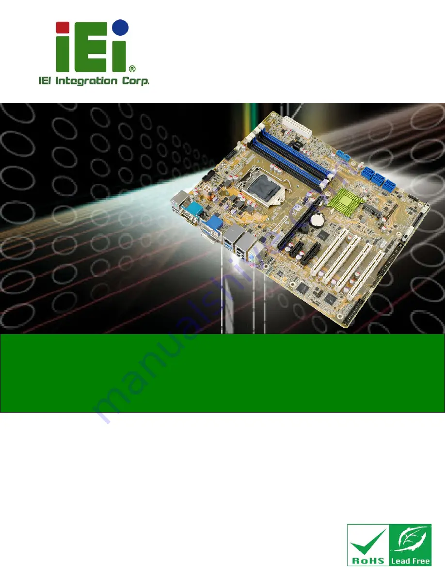
ATX Motherboard with LGA1150 Intel® Core

™

 i7/i5/i3,

Pentium® or Celeron® CPU, Intel® Q87 Chipset, Dual GbE,   

DDR3, DVI, HDMI, DisplayPort, VGA, USB 3.0, COM Ports   

Six SATA 6Gb/s Ports, IPMI 2.0 and RoHS 

Rev. 1.03 – December 13, 2016 

Summary of Contents for IMBA-Q870-i2

Page 1: ...r Manual MODEL IMBA Q870 i2 ATX Motherboard with LGA1150 Intel Core i7 i5 i3 Pentium or Celeron CPU Intel Q87 Chipset Dual GbE DDR3 DVI HDMI DisplayPort VGA USB 3 0 COM Ports Six SATA 6Gb s Ports IPMI...

Page 2: ...ges December 13 2016 1 03 Modified the max supported resolution of the DVI D connector Table 1 1 September 6 2016 1 02 Modified the system fan connector 2 SYS_FAN2 pinouts Table 3 13 March 13 2014 1 0...

Page 3: ...ages arising out of the use or inability to use the product or documentation even if advised of the possibility of such damages This document contains proprietary information protected by copyright Al...

Page 4: ...UTION Cautionary messages should be heeded to help reduce the chance of losing data or damaging the product NOTE These messages inform the reader of essential but non critical information These messag...

Page 5: ...13 3 CONNECTORS 16 3 1 PERIPHERAL INTERFACE CONNECTORS 17 3 1 1 IMBA Q870 i2 Layout 17 3 1 2 Peripheral Interface Connectors 18 3 1 3 External Interface Panel Connectors 19 3 2 INTERNAL PERIPHERAL CON...

Page 6: ...3 2 25 SPI Flash Connector EC 45 3 2 26 TPM Connector 46 3 2 27 USB 2 0 Connectors 47 3 2 28 USB 3 0 Connector 48 3 3 EXTERNAL PERIPHERAL INTERFACE CONNECTOR PANEL 49 3 3 1 Audio Connector 50 3 3 2 Ke...

Page 7: ...ection 75 4 5 3 HDMI Display Device Connection 76 4 5 4 LAN Connection 77 4 5 5 PS 2 Keyboard and Mouse Connection 78 4 5 6 Serial Device Connection 79 4 5 7 USB Connection Dual Connector 80 4 5 8 VGA...

Page 8: ...PSET 117 5 4 1 PCH IO Configuration 118 5 4 1 1 PCI Express Configuration 120 5 4 1 2 PCH Azalia Configuration 121 5 4 2 System Agent SA Configuration 121 5 4 2 1 Graphics Configuration 122 5 4 2 2 NB...

Page 9: ...IMBA Q870 i2 ATX Motherboard Page ix A REGULATORY COMPLIANCE 154 B PRODUCT DISPOSAL 156 C BIOS OPTIONS 158 D DIGITAL I O INTERFACE 162 E WATCHDOG TIMER 165 F HAZARDOUS MATERIALS DISCLOSURE 168...

Page 10: ...or Location 28 Figure 3 10 CPU Fan Connector Location 29 Figure 3 11 System Fan Connector Locations 30 Figure 3 12 Front Panel Audio Connector Location 31 Figure 3 13 Front Panel Connector Location 32...

Page 11: ...llation 65 Figure 4 8 iRIS 2400 Module Installation 66 Figure 4 9 Remove the Retention Screws for the mSATA Card 67 Figure 4 10 Insert the mSATA Card into the Socket at an Angle 68 Figure 4 11 Secure...

Page 12: ...dows Control Panel 140 Figure 6 14 System Control Panel 141 Figure 6 15 Device Manager List 142 Figure 6 16 Update Driver Software Window 143 Figure 6 17 Locate Driver Files 143 Figure 6 18 LAN Driver...

Page 13: ...3 11 CPU Fan Connector Pinouts 29 Table 3 12 System Fan Connector 1 Pinouts SYS_FAN1 30 Table 3 13 System Fan Connector 2 Pinouts SYS_FAN2 30 Table 3 14 Front Panel Audio Connector Pinouts 31 Table 3...

Page 14: ...3 35 USB 3 0 Port Pinouts 53 Table 3 36 LAN1 Pinouts 53 Table 3 37 HDMI Connector Pinouts 54 Table 3 38 Serial Port Connector Pinouts 54 Table 3 39 VGA Connector Pinouts 55 Table 3 40 DVI Connector Pi...

Page 15: ...n Configuration Menu 103 BIOS Menu 13 Parallel Port Configuration Menu 109 BIOS Menu 14 iWDD H W Monitor 111 BIOS Menu 15 Smart Fan Mode Configuration 112 BIOS Menu 16 Serial Port Console Redirection...

Page 16: ......

Page 17: ...IMBA Q870 i2 ATX Motherboard Page 1 Chapter 1 1 Introduction...

Page 18: ...ts for triple independent display Expansion and I O include four PCI slots one PCIe x16 slot one PCIe x4 slot with x1 signal one PCIe x1 slot two USB 3 0 ports on the rear panel two USB 3 0 ports by p...

Page 19: ...o 32 0 GB memory HDMI DisplayPort DVI D and VGA interfaces support triple independent display Supports IPMI 2 0 via IEI iRIS 2400 module Two Intel PCIe GbE connectors LAN1 with Intel AMT 9 0 support S...

Page 20: ...IMBA Q870 i2 ATX Motherboard Page 4 1 4 Connectors The connectors on the IMBA Q870 i2 are shown in the figure below Figure 1 2 IMBA Q870 i2 Connectors...

Page 21: ...IMBA Q870 i2 ATX Motherboard Page 5 1 5 Dimensions The main dimensions of the IMBA Q870 i2 are shown in the diagram below Figure 1 3 IMBA Q870 i2 Dimensions mm...

Page 22: ...IMBA Q870 i2 ATX Motherboard Page 6 1 6 Data Flow 6Figure 1 4 shows the data flow between the system chipset the CPU and other components installed on the motherboard Figure 1 4 Data Flow Diagram...

Page 23: ...333 1066 MHz dual channel DDR3 SDRAM DIMMs support up to 32 0 GB maximum Audio Realtek ALC662 HD Audio codec line in line out mic in BIOS UEFI BIOS Digital I O 8 bit 4 bit input 4 bit output Ethernet...

Page 24: ...use One internal keyboard and mouse connector One PS 2 keyboard and mouse connector TPM One TPM connector via 20 pin header Serial Ports One external RS 232 serial port One RS 422 485 via internal waf...

Page 25: ...d Page 9 Specification Model IMBA Q870 i2 Operating Temperature 20 C 60 C 4 F 140 F Humidity 5 95 non condensing Physical Specifications Dimensions 244 mm x 305 mm Weight GW NW 1200 g 700 g Table 1 1...

Page 26: ...IMBA Q870 i2 ATX Motherboard Page 10 Chapter 2 2 Packing List...

Page 27: ...ic discharge Self grounding Touch a grounded conductor every few minutes to discharge any excess static buildup Use an anti static pad When configuring any circuit board place it on an anti static mat...

Page 28: ...ler or vendor the IMBA Q870 i2 was purchased from or contact an IEI sales representative directly by sending an email to 33sales ieiworld com The IMBA Q870 i2 is shipped with the following components...

Page 29: ...separately purchased Item and Part Number Image IPMI 2 0 adapter card with AST2400 BMC chip P N iRIS 2400 R10 Dual port USB cable with bracket P N 19800 003100 300 RS Dual port USB 3 0 cable with brac...

Page 30: ...73W P N CF 1156A RS R11 LGA1155 LGA1156 cooler kit 95W P N CF 1156E R11 DisplayPort to HDMI converter board for IEI IDP connector P N DP HDMI R10 DisplayPort to 24 bit dual channel LVDS converter boar...

Page 31: ...board Page 15 Item and Part Number Image DisplayPort to DisplayPort converter board for iEi IDP connector P N DP DP R10 20 pin Infineon TPM Module S W management tool firmware V3 17 P N TPM IN01 R11 T...

Page 32: ...IMBA Q870 i2 ATX Motherboard Page 16 Chapter 3 3 Connectors...

Page 33: ...therboard Page 17 3 1 Peripheral Interface Connectors This chapter details all the jumpers and connectors 3 1 1 IMBA Q870 i2 Layout The figures below show all the connectors and jumpers Figure 3 1 Con...

Page 34: ...connector 19 pin box header DP1 EC debug connector 18 pin header CN3 Fan connector CPU 4 pin wafer CPU_FAN1 Fan connectors system 3 pin wafer SYS_FAN1 SYS_FAN2 Front panel audio connector 10 pin heade...

Page 35: ...4 SMBus connector 4 pin wafer CN1 SPI flash connector 8 pin header JSPI1 SPI flash connector EC 8 pin header JSPI2 TPM connector 20 pin header TPM1 USB 2 0 connectors 8 pin headers USB1 USB2 USB 3 0 c...

Page 36: ...1 Table 3 2 Rear Panel Connectors 3 2 Internal Peripheral Connectors The section describes all of the connectors on the IMBA Q870 i2 3 2 1 Additional Power Connector CN Label ATXPWR1 CN Type 4 pin con...

Page 37: ...Pinouts 3 2 2 ATX Power Connector CN Label ATX1 CN Type 24 pin ATX p 4 2 mm CN Location See Figure 3 3 CN Pinouts See Table 3 4 The ATX power connector connects to an ATX power supply Figure 3 3 ATX...

Page 38: ...tor CAUTION Risk of explosion if battery is replaced by an incorrect type Only certified engineers should replace the on board battery Dispose of used batteries according to instructions and local reg...

Page 39: ...le 3 5 Battery Connector Pinouts 3 2 4 Chassis Intrusion Connector CN Label CHASSIS1 CN Type 2 pin header p 2 54 mm CN Location See 7Figure 3 5 CN Pinouts See 7Table 3 6 The chassis intrusion connecto...

Page 40: ...ocation Pin Description 1 3 3VSB 2 CHASSIS OPEN Table 3 6 Chassis Intrusion Connector Pinouts 3 2 5 CPU Power Connector CN Label CPU12V1 CN Type 4 pin connector p 4 2 mm CN Location See Figure 3 6 CN...

Page 41: ...ND 3 12V 4 12V Table 3 7 CPU Power Connector Pinouts 3 2 6 DisplayPort Connector CN Label DP1 CN Type 19 pin box header p 2 0 mm CN Location See Figure 3 7 CN Pinouts See Table 3 8 The DisplayPort con...

Page 42: ...2N 6 LANE3P 16 GND 7 GND 17 LANE0P 8 AUX_CTRL_DET_D 18 LANE0N 9 GND 19 3 3V 10 HPD Table 3 8 DisplayPort Connector Pinouts 3 2 7 Digital I O Connector CN Label DIO1 CN Type 10 pin header p 2 54 mm CN...

Page 43: ...ion 1 GND 2 VCC 3 Output 3 4 Output 2 5 Output 1 6 Output 0 7 Input 3 8 Input 2 9 Input 1 10 Input 0 Table 3 9 Digital I O Connector Pinouts 3 2 8 EC Debug Connector CN Label CN3 CN Type 18 pin header...

Page 44: ...P_INIT 7 EC_EPP_PD2 8 EC_EPP_SLIN 9 EC_EPP_PD3 10 GND 11 EC_EPP_PD4 12 NC 13 EC_EPP_PD5 14 EC_EPP_BUSY 15 EC_EPP_PD6 16 EC_EPP_KSI5 17 EC_EPP_PD7 18 EC_EPP_KSI4 Table 3 10 EC Debug Connector Pinouts 3...

Page 45: ...escription 1 GND 2 12 V 3 FANIO 4 PWM Table 3 11 CPU Fan Connector Pinouts 3 2 10 Fan Connectors System CN Label SYS_FAN1 SYS_FAN2 CN Type 3 pin wafer p 2 54 mm CN Location See Figure 3 11 CN Pinouts...

Page 46: ...Page 30 Figure 3 11 System Fan Connector Locations Pin Description 1 FANIO 2 12 V PWM 3 GND Table 3 12 System Fan Connector 1 Pinouts SYS_FAN1 Pin Description 1 NC 2 12 V 3 GND Table 3 13 System Fan...

Page 47: ...ion See Figure 3 12 CN Pinouts See Table 3 14 This connector connects to speakers a microphone and an audio input Figure 3 12 Front Panel Audio Connector Location Pin Description Pin Description 1 MIC...

Page 48: ...connects to the indicator LEDs and buttons on the computer s front panel Figure 3 13 Front Panel Connector Location Function Pin Description Function Pin Description Power LED 1 5V Speaker 2 Beep Pow...

Page 49: ...module slot is used to install the IEI iRIS 2400 IPMI 2 0 module Please refer to Section 4 7 for IPMI setup procedure WARNING The iRIS module slot is designed to install the IEI iRIS 2400 IPMI 2 0 mod...

Page 50: ...on See Figure 3 15 CN Pinouts See Table 3 16 The keyboard mouse connector connects to a PS 2 Y cable that can be connected to a PS 2 keyboard and mouse Figure 3 15 Keyboard and Mouse Location Pin Desc...

Page 51: ...nd Table 3 18 The LAN LED connectors are used to connect to the LAN LED indicators on the chassis to indicate users the link activities of the two LAN ports Figure 3 16 LAN LED Connector Locations Pin...

Page 52: ...e DDR3 DIMM slot CN Location See 7Figure 3 17 The DIMM slots are for DDR3 DIMM memory modules Figure 3 17 Memory Card Slot Locations 3 2 17 mSATA Card Slot CN Label CN2 CN Type PCIe Mini slot CN Locat...

Page 53: ...onnector will be disabled Please refer to Section 4 3 4 Figure 3 18 mSATA Card Slot Location Pin Description Pin Description 1 PCIE_WAKE 2 3 3V 3 N C 4 GND 5 N C 6 1 5V 7 N C 8 N C 9 GND 10 N C 11 MSA...

Page 54: ...43 3 3V 44 N C 45 CLINK_CLK 46 N C 47 CLINK_DATA 48 1 5V 49 CLINK_RST 50 GND 51 MSATA_DET 52 3 3V Table 3 19 mSATA Card Slot Pinouts 3 2 18 Parallel Port Connector CN Label LPT1 CN Type 26 pin box hea...

Page 55: ...TA 4 7 DATA 5 8 DATA 6 9 DATA 7 10 ACKNOWLEDGE 11 BUSY 12 PAPER EMPTY 13 PRINTER SELECT 14 AUTO FORM FEED 15 ERROR 16 INITIALIZE 17 PRINTER SELECT LN 18 GROUND 19 GROUND 20 GROUND 21 GROUND 22 GROUND...

Page 56: ...r Button Location 3 2 20 SATA 6Gb s Drive Connectors CN Label S_ATA1 S_ATA2 S_ATA3 S_ATA4 S_ATA5 S_ATA6 CN Type 7 pin SATA drive connectors CN Location See Figure 3 21 CN Pinouts See Table 3 21 The SA...

Page 57: ...If the user shorts the mSATA Slot Setup jumper MSATA_SW1 to force the system to enable mSATA device the S_ATA6 connector will be disabled Please refer to Section 4 3 4 3 2 21 Serial Port Connectors RS...

Page 58: ...3 RXD 4 RTS COM2 5 TXD 6 CTS 7 DTR 8 RI 9 GND 10 GND 11 DCD 12 DSR 13 RXD 14 RTS COM3 15 TXD 16 CTS 17 DTR 18 RI 19 GND 20 GND 21 DCD 22 DSR 23 RXD 24 RTS COM5 25 TXD 26 CTS 27 DTR 28 RI 29 GND 30 GN...

Page 59: ...Figure 3 23 CN Pinouts See Table 3 23 Used for RS 422 485 communications Figure 3 23 RS 422 485 Connector Location Pin Description 1 RXD422 2 RXD422 3 TXD422 TXD485 4 TXD422 TXD485 Table 3 23 RS 422 4...

Page 60: ...nector CN Label CN1 CN Type 4 pin wafer p 1 25 mm CN Location See Figure 3 24 CN Pinouts See Table 3 25 The SMBus System Management Bus connector provides low speed system management communications Fi...

Page 61: ...or is used to flash the SPI ROM Figure 3 25 SPI Flash Connector Location Pin Description Pin Description 1 3 3V 2 SPI_CS 3 SPI_SO 4 NC 5 GND 6 SPI_CLK 7 SPI_SI 8 NC Table 3 26 SPI Flash Connector Pino...

Page 62: ...ription Pin Description 1 3 3V 2 SPI_CS 3 SPI_SO 4 NC 5 GND 6 SPI_CLK 7 SPI_SI 8 NC Table 3 27 SPI EC Flash Connector Pinouts 3 2 26 TPM Connector CN Label TPM1 CN Type 20 pin header p 2 54 mm CN Loca...

Page 63: ...AD2 9 3 3V 10 LAD1 11 LAD0 12 GND 13 SCL 14 SDA 15 SB3V 16 SERIRQ 17 GND 18 GLKRUN 19 LPCPD 20 LDRQ Table 3 28 TPM Connector Pinouts 3 2 27 USB 2 0 Connectors CN Label USB1 USB2 CN Type 8 pin header p...

Page 64: ...GND 3 USB_DATA 4 USB_DATA 5 USB_DATA 6 USB_DATA 7 GND 8 VCC Table 3 29 USB 2 0 Connector Pinouts 3 2 28 USB 3 0 Connector CN Label CN4 CN Type 19 pin box header p 2 0 mm CN Location See Figure 3 29 C...

Page 65: ...ATA 3 USB3_RX 13 GND 4 GND 14 USB3_TX 5 USB3_TX 15 USB3_TX 6 USB3_TX 16 GND 7 GND 17 USB3_RX 8 USB_DATA 18 USB3_RX 9 USB_DATA 19 VCC 10 NC Table 3 30 USB 3 0 Connector Pinouts 3 3 External Peripheral...

Page 66: ...Location See Figure 3 30 The audio jacks connect to external audio devices Line In port Light Blue Connects a CD ROM DVD player or other audio devices Line Out port Lime Connects to a headphone or a s...

Page 67: ...n Pin Description 1 VCC 5 VCC 2 USB_DATA 6 USB_DATA 3 USB_DATA 7 USB_DATA 4 GND 8 GND Table 3 31 USB 2 0 Port Pinouts The PS 2 port is for connecting a PS 2 mouse and a PS 2 keyboard Pin Description 9...

Page 68: ...n Description Pin Description P2 TRD2P0 P6 TRD2P2 P3 TRD2N0 P7 TRD2N2 P4 TRD2P1 P8 TRD2P3 P5 TRD2N1 P9 TRD2N3 Table 3 34 LAN2 Pinouts 3 3 4 Ethernet and USB 3 0 Connectors CN Label LAN1_USB1 CN Type R...

Page 69: ...scription 20 LAN1_MDI0P 24 LAN1_MDI2P 21 LAN1_MDI0N 25 LAN1_MDI2N 22 LAN1_MDI1P 26 LAN1_MDI3P 23 LAN1_MDI1N 27 LAN1_MDI3N Table 3 36 LAN1 Pinouts 3 3 5 HDMI Port Connector CN Label HDMI1 CN Type HDMI...

Page 70: ...Connector Pinouts 3 3 6 Serial Port Connector COM1 CN Label COM1 CN Type DB 9 connector CN Location See Figure 3 30 CN Pinouts See Table 3 38 The serial port connects to a RS 232 serial communications...

Page 71: ...monitor that accepts a standard VGA input Pin Description Pin Description V1 RED V2 GREEN V3 BLUE V4 NC V5 GND V6 GND V7 GND V8 GND V9 VCC V10 GND V11 NC V12 DDCDA V13 HSYNC V14 VSYNC V15 DDCCLK Table...

Page 72: ...on C5 GND 14 5V C6 NC 15 Hot Plug Detect 1 DVI_DATA2 16 HPDET 2 DVI_DATA2 17 DVI_DATA0 3 GND 18 DVI_DATA0 4 N C 19 GND 5 N C 20 N C 6 DDC CLK 21 N C 7 DDC DATA 22 N C 8 VS 23 DVI_CLK 9 DVI_DATA1 24 DV...

Page 73: ...IMBA Q870 i2 ATX Motherboard Page 57 Chapter 4 4 Installation...

Page 74: ...ristband can help to prevent ESD from damaging the board Self grounding Before handling the board touch any grounded conducting material During the time the board is handled frequently touch any condu...

Page 75: ...the body and helps prevent ESD damage Place the IMBA Q870 i2 on an antistatic pad o When installing or configuring the motherboard place it on an antistatic pad This helps to prevent potential ESD dam...

Page 76: ...talled DO NOT touch the pins at the bottom of the CPU When handling the CPU only hold it on the sides To install the CPU follow the steps below Step 1 Disengage the load lever by pressing the lever do...

Page 77: ...ir Step 4 Orientate the CPU properly The contact array should be facing the CPU socket WARNING DO NOT touch the pins at the bottom of the CPU When handling the CPU only hold it on the sides Step 5 Cor...

Page 78: ...hly See Figure 4 3 Figure 4 3 Insert the Socket LGA1150 CPU Step 8 Close the CPU socket Close the load plate and pull the load lever back a little to have the load plate be able to secure to the knob...

Page 79: ...nts the board from bending and is ONLY compatible with captive screw type cooling fans Figure 4 5 Cooling Kits CF 1156A RS and CF 1156E RS The cooling kit can be bought from IEI The cooling kit has a...

Page 80: ...g kit is installed Step 3 Mount the cooling kit Gently place the cooling kit on top of the CPU Make sure the four threaded screws on the corners of the cooling kit properly pass through the holes of t...

Page 81: ...far as they can See Figure 4 7 Step 2 Align the DIMM with the socket Align the DIMM so the notch on the memory lines up with the notch on the memory socket See Figure 4 7 Step 3 Insert the DIMM Once...

Page 82: ...lease follow the steps below and refer to Figure 4 7 Figure 4 8 iRIS 2400 Module Installation Step 1 Open the socket handles Open the two handles outwards as far as they can See Figure 4 7 Step 2 Alig...

Page 83: ...s 4 2 5 mSATA Card Installation To install a mSATA card please follow the steps below Step 1 Locate the mSATA card slot The location of the mSATA card slot is shown in Chapter 3 Step 2 Remove the rete...

Page 84: ...re the mSATA card Secure the mSATA card with the retention screws previously removed 7Figure 4 11 Step 0 Figure 4 11 Secure the mSATA Card 4 3 System Configuration The system configuration is controll...

Page 85: ...AT ATX power mode switch which is shown in Figure 4 12 Figure 4 12 AT ATX Power Mode Switch Location 4 3 2 Clear CMOS Button To reset the BIOS remove the on board battery and press the clear CMOS but...

Page 86: ...14 Flash Descriptor Security Override Jumper Location 4 3 4 mSATA Slot Setup The mSATA Slot Setup jumper p 2 0 mm specifies whether to automatically detect the mSATA device installed in the mSATA car...

Page 87: ...x16 PCIE Sets the PCIe x16 slot as one PCIe x16 Default Table 4 3 PCIe x16 Interface Setup Please refer to Section 5 4 1 for detailed information 4 3 6 USB Power Select The USB power selection is made...

Page 88: ...on 4 4 Internal Peripheral Device Connections This section outlines the installation of peripheral devices to the onboard connectors 4 4 1 SATA Drive Connection The IMBA Q870 i2 is shipped with two SA...

Page 89: ...ep 3 Connect the cable to the SATA disk Connect the connector on the other end of the cable to the connector at the back of the SATA drive See Figure 4 17 Step 4 Connect the SATA power cable optional...

Page 90: ...ctor The audio jacks on the external audio connector enable the IMBA Q870 i2 to be connected to a stereo sound setup Each jack supports both input and output When connecting a device the High Definiti...

Page 91: ...t to rear and left to right 4 5 2 DVI Display Device Connection The IMBA Q870 i2 has a single female DVI I connector on the external peripheral interface panel The DVI I connector is connected to a di...

Page 92: ...the digital display device to the external interface by tightening the two retention screws on either side of the connector Step 0 4 5 3 HDMI Display Device Connection The HDMI connector transmits a d...

Page 93: ...is being inserted with the right way up Step 0 4 5 4 LAN Connection There are two external RJ 45 LAN connectors The RJ 45 connectors enable connection to an external network To connect a LAN cable wi...

Page 94: ...nnector on the external peripheral interface panel The PS 2 connector is used to connect to a keyboard or a mouse to the system Follow the steps below to connect a keyboard or a mouse to the IMBA Q870...

Page 95: ...ernal peripheral interface panel for a serial device Follow the steps below to connect a serial device to the IMBA Q870 i2 Step 1 Locate the DB 9 connector The location of the DB 9 connector is shown...

Page 96: ...ector The external USB Series A receptacle connectors provide easier and quicker access to external USB devices Follow the steps below to connect USB devices to the IMBA Q870 i2 Step 1 Locate the USB...

Page 97: ...lease follow the instructions below Step 1 Locate the female DB 15 connector The location of the female DB 15 connector is shown in Chapter 3 Step 2 Align the VGA connector Align the male DB 15 connec...

Page 98: ...e Intel AMT function follow the steps below Step 1 Make sure at least one of the memory sockets is installed with a DDR3 DIMM Step 2 Connect an Ethernet cable to the RJ 45 connector labeled LAN1 Step...

Page 99: ...management by enabling users to maximize IT resources save time and manage multiple systems The IMBA Q870 i2 supports IPMI 2 0 through the optional iRIS 2400 module Follow the steps below to setup IP...

Page 100: ...USB flash drive d Enter the following command ipmitool 20 30 02 01 03 00 00 there is a space between each two digit number e A serial of number shows The last four two digit hexadecimal numbers are th...

Page 101: ...ge 85 Figure 4 27 IEI iMAN Web GUI NOTE To understand how to use the IEI iMAN Web GUI please refer to the iRIS 2400 Web GUI user manual in the utility CD came with the IMBA Q870 i2 The user manual des...

Page 102: ...IMBA Q870 i2 ATX Motherboard Page 86 Chapter 5 5 BIOS...

Page 103: ...n one of two ways 1 Press the DEL or F2 key as soon as the system is turned on or 2 Press the DEL or F2 key when the Press DEL or F2 to enter SETUP message appears on the screen If the message disappe...

Page 104: ...BIOS Navigation Keys When F1 is pressed a small help window describing the appropriate keys to use and the possible selections for the highlighted item appears To exit the Help Window press ESC or the...

Page 105: ...loads default settings The following sections completely describe the configuration options found in the menu items at the top of the BIOS screen and listed above 5 2 Main The Main BIOS menu BIOS Men...

Page 106: ...z IGFX VBIOS Version 2178 Memory RC Version 1 6 2 1 Total Memory 4096 MB DDR3 Memory Frequency 1333 Mhz PCH Information Name LynxPoint PCH SKU Q87 Stepping 05 C2 LAN PHY Revision A3 ME FW Version 9 0...

Page 107: ...malfunction Make sure that the settings made are compatible with the hardware Aptio Setup Utility Copyright C 2012 American Megatrends Inc Main Advanced Chipset Boot Security Save Exit ACPI Settings...

Page 108: ...2 Previous Values F3 Optimized Defaults F4 Save Exit ESC Exit Version 2 11 1210 Copyright C 2011 American Megatrends Inc BIOS Menu 3 ACPI Configuration ACPI Sleep State S1 CPU Stop Clock Use the ACPI...

Page 109: ...system wake on alarm event When enabled system will wake on the date hr min sec specified Select Screen Select Item EnterSelect Change Opt F1 General Help F2 Previous Values F3 Optimized Defaults F4 S...

Page 110: ...he Trusted Computing Group TCG Trusted Platform Module TPM Aptio Setup Utility Copyright C 2012 American Megatrends Inc Advanced Configuration Security Device Support Disabled Current TPM Status Infor...

Page 111: ...d Intel SMX Technology Not Supported 64 bit Supported EIST Technology Supported L1 Data ache 32 kB x 2 L1 Code Cache 32 kB x 2 L2 Cache 256 kB x 2 L3 Cache 4096 kB Hyper Threading Enabled Active Proce...

Page 112: ...ed Intel SpeedStep Techonology is supported by the CPU L1 Data Cache Lists the amount of data storage space on the L1 cache L1 Code Cache Lists the amount of code storage space on the L1 cache L2 Cach...

Page 113: ...e Intel Virtualization technology allows several OSs to run on the same system at the same time Disabled DEFAULT Disables Intel Virtualization Technology Enabled Enables Intel Virtualization Technolog...

Page 114: ...ect Item EnterSelect Change Opt F1 General Help F2 Previous Values F3 Optimized Defaults F4 Save Exit ESC Exit Version 2 15 1236 Copyright C 2012 American Megatrends Inc BIOS Menu 7 SATA Configuration...

Page 115: ...Rapid Start Technology Select Screen Select Item EnterSelect Change Opt F1 General Help F2 Previous Values F3 Optimized Defaults F4 Save Exit ESC Exit Version 2 15 1236 Copyright C 2012 American Megat...

Page 116: ...ion execution If enabled this requires additional firmware in the SPI device Select Screen Select Item EnterSelect Change Opt F1 General Help F2 Previous Values F3 Optimized Defaults F4 Save Exit ESC...

Page 117: ...Item EnterSelect Change Opt F1 General Help F2 Previous Values F3 Optimized Defaults F4 Save Exit ESC Exit Version 2 15 1236 Copyright C 2012 American Megatrends Inc BIOS Menu 10 USB Configuration US...

Page 118: ...Utility Copyright C 2012 American Megatrends Inc Advanced F81866 Super IO Configuration F81866 Super IO Chip F81866 Serial Port 1 Configuration Serial Port 2 Configuration Serial Port 3 Configuration...

Page 119: ...ues F3 Optimized Defaults F4 Save Exit ESC Exit Version 2 15 1236 Copyright C 2012 American Megatrends Inc BIOS Menu 12 Serial Port n Configuration Menu 5 3 9 1 1 Serial Port 1 Configuration Serial Po...

Page 120: ...Enable the serial port Change Settings Auto Use the Change Settings option to change the serial port IO port address and interrupt address Auto DEFAULT The serial port IO port address and interrupt a...

Page 121: ...he serial port IO port address and interrupt address Auto DEFAULT The serial port IO port address and interrupt address are automatically detected IO 2D0h IRQ 10 Serial Port I O port address is 2D0h a...

Page 122: ...O port address is 3E8h and the interrupt address is IRQ10 11 IO 2E8h IRQ 10 11 Serial Port I O port address is 2E8h and the interrupt address is IRQ10 11 IO 2D0h IRQ 10 11 Serial Port I O port addres...

Page 123: ...ress is 2C0h and the interrupt address is IRQ10 11 IO 2C8h IRQ 10 11 Serial Port I O port address is 2C8h and the interrupt address is IRQ10 11 IO 2D0h IRQ 10 11 Serial Port I O port address is 2D0h a...

Page 124: ...and the interrupt address is IRQ10 IO 2C0h IRQ 10 11 Serial Port I O port address is 2C0h and the interrupt address is IRQ10 11 IO 2C8h IRQ 10 11 Serial Port I O port address is 2C8h and the interrupt...

Page 125: ...d Defaults F4 Save Exit ESC Exit Version 2 15 1236 Copyright C 2012 American Megatrends Inc BIOS Menu 13 Parallel Port Configuration Menu Parallel Port Enabled Use the Parallel Port option to enable o...

Page 126: ...e STD Printer Mode Use the Device Mode option to select the mode the parallel port operates in Configuration options are listed below STD Printer Mode Default SPP Mode EPP 1 9 and SPP Mode EPP 1 7 and...

Page 127: ...3 074 V Smart FAN Configuration Select Screen Select Item EnterSelect Change Opt F1 General Help F2 Previous Values F3 Optimized Defaults F4 Save Exit ESC Exit Version 2 15 1236 Copyright C 2012 Amer...

Page 128: ...30 Fan slope PWM 1 Smart Fan Mode Select Select Screen Select Item EnterSelect Change Opt F1 General Help F2 Previous Values F3 Optimized Defaults F4 Save Exit ESC Exit Version 2 15 1236 Copyright C 2...

Page 129: ...or key to change the Fan slope PWM value Enter a decimal number between 1 and 64 5 3 11 Serial Port Console Redirection The Serial Port Console Redirection menu BIOS Menu 16 allows the console redirec...

Page 130: ...n Settings iAMT SOL COM8 Pci Bus0 Dev22 Func3 Console Redirection Disabled Console Redirection Settings Console Redirection Enable or Disable Select Screen Select Item EnterSelect Change Opt F1 Genera...

Page 131: ...s may require lower speeds 9600 Sets the serial port transmission speed at 9600 19200 Sets the serial port transmission speed at 19200 57600 Sets the serial port transmission speed at 57600 115200 DEF...

Page 132: ...ets the number of stop bits at 1 2 Sets the number of stop bits at 2 5 3 12 iEi Feature Use the iEi Feature menu BIOS Menu 17 to configure IEI One Key Recovery function Aptio Setup Utility Copyright C...

Page 133: ...stem Agent SA Subsystem configuration menus WARNING Setting the wrong values for the Chipset BIOS selections in the Chipset BIOS menu may cause the system to malfunction Aptio Setup Utility Copyright...

Page 134: ...Previous Values F3 Optimized Defaults F4 Save Exit ESC Exit Version 2 15 1236 Copyright C 2012 American Megatrends Inc BIOS Menu 19 PCH IO Configuration Restore on AC Power Loss Last State Use the Re...

Page 135: ...5V Set the USB power source to 5V 5V DUAL DEFAULT Set the USB power source to 5V dual USB SW2 Power 5V DUAL Use the USB SW2 Power BIOS option to configure the USB power source for the corresponding U...

Page 136: ...Version 2 15 1236 Copyright C 2012 American Megatrends Inc BIOS Menu 20 PCI Express Configuration PCIe Speed Gen1 Use the PCIe Speed option to specify the PCI Express port speed Configuration options...

Page 137: ...reen Select Item EnterSelect Change Opt F1 General Help F2 Previous Values F3 Optimized Defaults F4 Save Exit ESC Exit Version 2 15 1236 Copyright C 2012 American Megatrends Inc BIOS Menu 21 PCH Azali...

Page 138: ...gatrends Inc BIOS Menu 22 System Agent SA Configuration 5 4 2 1 Graphics Configuration Use the Graphics Configuration submenu BIOS Menu 23 to configure the graphics settings Aptio Setup Utility Copyri...

Page 139: ...can be used by the internal graphics device 32M 32 MB of memory used by internal graphics device 64M 64 MB of memory used by internal graphics device 128M 128 MB of memory used by internal graphics d...

Page 140: ...al graphics present Secondary boot display selection will appear based on your selection VGA modes will be supported only on primary display Select Screen Select Item Enter Select Change Opt F1 Genera...

Page 141: ...e Device Enabled Select Screen Select Item EnterSelect Change Opt F1 General Help F2 Previous Values F3 Optimized Defaults F4 Save Exit ESC Exit Version 2 15 1236 Copyright C 2012 American Megatrends...

Page 142: ...Memory Configuration submenu BIOS Menu 26 to configure the Memory settings Aptio Setup Utility Copyright C 2012 American Megatrends Inc Chipset Memory Information Total Memory 4096 MB DDR3 CHA_DIMM1...

Page 143: ...ersion 2 15 1236 Copyright C 2012 American Megatrends Inc BIOS Menu 27 Boot Bootup NumLock State On Use the Bootup NumLock State BIOS option to specify if the number lock setting must be modified duri...

Page 144: ...to set the Option ROM display mode Force BIOS DEFAULT Sets display mode to force BIOS Keep Current Sets display mode to current Launch PXE OpROM Disabled Use the Launch PXE OpROM option to enable or d...

Page 145: ...tup the User will have Administrator rights The password must be In the following range Maximum length 3 Minimum length 20 Administrator Password User Password Set Administrator Password Select Screen...

Page 146: ...Menu 29 Exit Save Changes and Reset Use the Save Changes and Reset option to save the changes made to the BIOS options and reset the system Discard Changes and Reset Use the Discard Changes and Reset...

Page 147: ...IMBA Q870 i2 ATX Motherboard Page 131 6 Software Drivers Chapter 6...

Page 148: ...can be installed on the system Chipset Graphics LAN USB 3 0 Audio Intel AMT Installation instructions are given below 6 2 Software Installation All the drivers for the IMBA Q870 i2 are on the CD that...

Page 149: ...ard Page 133 Figure 6 1 Introduction Screen Step 3 Click IMBA Q870 Step 4 A new screen with a list of available drivers appears Figure 6 2 Figure 6 2 Available Drivers Step 5 Install all of the necess...

Page 150: ...ion 6 2 Step 2 Click 1 Chipset Step 3 Locate the setup file and double click on it Step 4 When the setup files are completely extracted the Welcome Screen in Figure 6 3 appears Step 5 Click Next to co...

Page 151: ...icense Agreement Step 9 The Read Me file in Figure 6 5 appears Step 10 Click Next to continue Figure 6 5 Chipset Driver Read Me File Step 11 Setup Operations are performed as shown in Figure 6 6 Step...

Page 152: ...age 136 Figure 6 6 Chipset Driver Setup Operations Step 13 The Finish screen in Figure 6 7 appears Step 14 Select Yes I want to restart this computer now and click Finish Step 0 Figure 6 7 Chipset Dri...

Page 153: ...6 2 Step 2 Click 2 Graphics and select the folder which corresponds to the operating system Step 3 Locate the setup file and double click on it Step 4 The Welcome Screen in Figure 6 8 appears Step 5 C...

Page 154: ...r License Agreement Step 8 The Read Me file in Figure 6 10 appears Click Next to continue Figure 6 10 Graphics Driver Read Me File Step 9 Setup Operations are performed as shown in Figure 6 11 Step 10...

Page 155: ...139 Figure 6 11 Graphics Driver Setup Operations Step 11 The Finish screen in Figure 6 12 appears Step 12 Select Yes I want to restart this computer now and click Finish Step 0 Figure 6 12 Graphics D...

Page 156: ...the LAN driver please do the following Step 1 Right click the Computer button from the start menu and select Properties Figure 6 13 Figure 6 13 Windows Control Panel Step 2 The system control panel wi...

Page 157: ...trol Panel Step 4 A list of system hardware devices appears Figure 6 15 Step 5 Right click one of the Ethernet controllers that has question marks next to it this means Windows does not recognize the...

Page 158: ...IMBA Q870 i2 ATX Motherboard Page 142 Figure 6 15 Device Manager List Step 7 The Update Driver Software Window appears Figure 6 16...

Page 159: ...y computer for driver software and click NEXT to continue Step 9 Click Browse to select X 3 LAN directory in the Locate File window where X is the system CD drive Figure 6 17 Figure 6 17 Locate Driver...

Page 160: ...6 Step 12 to install the second Ethernet controller driver Step 0 6 6 USB 3 0 Driver Installation WARNING Do not run this driver s installer Setup exe from a USB storage device ie external USB hard dr...

Page 161: ...p file and double click on it Step 4 A Welcome Screen appears Figure 6 19 Step 5 Click Next to continue Figure 6 19 USB 3 0 Driver Welcome Screen Step 6 The license agreement in Figure 6 20 appears St...

Page 162: ...cense Agreement Step 9 The Read Me file in Figure 6 21 appears Step 10 Click Next to continue Figure 6 21 USB 3 0 Driver Read Me File Step 11 Setup Operations are performed as shown in Figure 6 22 Ste...

Page 163: ...e 147 Figure 6 22 USB 3 0 Driver Setup Operations Step 13 The Finish screen in Figure 6 23 appears Step 14 Select Yes I want to restart this computer now and click Finish Step 0 Figure 6 23 USB 3 0 Dr...

Page 164: ...Press F10 to save the changes and exit the BIOS setup The system reboots Step 0 6 7 2 Driver Installation To install the audio driver please follow the steps below To install the audio driver please d...

Page 165: ...creen Step 6 Click Next to continue the installation Step 7 InstallShield starts to install the new software as shown in Figure 6 25 Figure 6 25 Audio Driver Software Configuration Step 8 After the dr...

Page 166: ...llation The package of the Intel ME components includes Intel Management Engine Interface Intel ME Interface Intel Dynamic Application Loader Intel Identity Protection Technology Intel IPT Serial Over...

Page 167: ...t Step 5 When the setup files are completely extracted the Welcome Screen in Figure 6 27 appears Step 6 Click Next to continue Figure 6 27 Intel ME Driver Welcome Screen Step 7 The license agreement i...

Page 168: ...up Operations are performed as shown in Figure 6 29 Step 11 Once the Setup Operations are complete click Next to continue Figure 6 29 Intel ME Driver Setup Operations Step 12 The Finish screen in Figu...

Page 169: ...IMBA Q870 i2 ATX Motherboard Page 153 Figure 6 30 Intel ME Driver Installation Finish Screen...

Page 170: ...IMBA Q870 i2 ATX Motherboard Page 154 Appendix A A Regulatory Compliance...

Page 171: ...nterference that may cause undesired operation This equipment has been tested and found to comply with the limits for a Class A digital device pursuant to part 15 of the FCC Rules These limits are des...

Page 172: ...IMBA Q870 i2 ATX Motherboard Page 156 B Product Disposal Appendix B...

Page 173: ...classified as electronic device in terms of the European Directive 2012 19 EU WEEE and must not be disposed of as domestic garbage EU wide legislation as implemented in each Member State requires that...

Page 174: ...IMBA Q870 i2 ATX Motherboard Page 158 Appendix C C BIOS Options...

Page 175: ...led 98 SATA Mode Selection IDE 98 Intel R Rapid Start Technology Disabled 99 Intel AMT Enabled 100 Unconfigure ME Disabled 100 USB Devices 101 Legacy USB Support Enabled 101 Serial Port Enabled 103 Ch...

Page 176: ...r Saving Function Disabled 118 PCIEX16 Power 1 x16 PCIE 119 USB SW1 Power 5V DUAL 119 USB SW2 Power 5V DUAL 119 PCIe Speed Gen1 120 Detect Non Compliance Device Enabled 120 Azalia Enabled 121 Primary...

Page 177: ...IMBA Q870 i2 ATX Motherboard Page 161 Discard Changes and Reset 130 Restore Defaults 130 Save as User Defaults 130 Restore User Defaults 130...

Page 178: ...IMBA Q870 i2 ATX Motherboard Page 162 Appendix D D Digital I O Interface...

Page 179: ...trol the on off circuit of external devices or TTL devices Data can be read or written to the selected address to enable the DIO functions NOTE For further information please refer to the datasheet fo...

Page 180: ...age 164 AH 6FH Sub function AL 9 Set the digital port as OUTPUT BL Digital I O output value Assembly Language Sample 2 MOV AX 6F09H setting the digital port as output MOV BL 09H digital value is 09H I...

Page 181: ...IMBA Q870 i2 ATX Motherboard Page 165 Appendix E E Watchdog Timer...

Page 182: ...INT 15H is used to control the Watchdog Timer INT 15H AH 6FH Sub function AL 2 Sets the Watchdog Timer s period BL Time out value Its unit second is dependent on the item Watchdog Timer unit select i...

Page 183: ...he system resets EXAMPLE PROGRAM INITIAL TIMER PERIOD COUNTER W_LOOP MOV AX 6F02H setting the time out value MOV BL 30 time out value is 48 seconds INT 15H ADD THE APPLICATION PROGRAM HERE CMP EXIT_AP...

Page 184: ...IMBA Q870 i2 ATX Motherboard Page 168 Appendix F F Hazardous Materials Disclosure...

Page 185: ...lamps These components will be separately marked Please refer to the following table Toxic or Hazardous Substances and Elements Part Name Lead Pb Mercury Hg Cadmium Cd Hexavalent Chromium CR VI Polyb...

Page 186: ...otherboard Page 170 RoHS RoHS Pb Hg Cd CR VI PBB PBDE O O O O O O O O O O O O O O O O O O O O O O O O O O O O O O O O O O O O O O O O O O O O O O O O O SJ T 11363 2006 GB T 26572 2011 X SJ T 11363 200...

Reviews: