IMBA-Q670 ATX Motherboard
Page 40
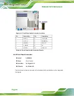
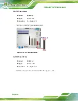
Figure 3-24: SPI Connector Location
PIN NO.
DESCRIPTION
PIN NO.
DESCRIPTION
1
+3.3V
2
GND
3
SPI_CS0
4
SPI_CLK
5
SPI_SO0
6
SPI_SI
7
NC
8
NC
Table 3-20: SPI Connector Pinouts
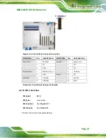
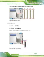
3.2.24 TPM Connector
CN Label:
TPM1
CN Type:
20-pin header
CN Location:
CN Pinouts:
The TPM connector connects to a TPM module.
Summary of Contents for IMBA-Q670
Page 14: ...IMBA Q670 ATX Motherboard Page xiv Figure B 43 Disable Automatically Restart 182...
Page 18: ......
Page 19: ...IMBA Q670 ATX Motherboard Page 1 Chapter 1 1 Introduction...
Page 27: ...IMBA Q670 ATX Motherboard Page 9 Chapter 2 2 Packing List...
Page 32: ...IMBA Q670 ATX Motherboard Page 14 Chapter 3 3 Connectors...
Page 66: ...IMBA Q670 ATX Motherboard Page 48 Chapter 4 4 Installation...
Page 89: ...IMBA Q670 ATX Motherboard Page 71 Chapter 5 5 BIOS...
Page 132: ...IMBA Q670 ATX Motherboard Page 114 6 Software Drivers Chapter 6...
Page 160: ...IMBA Q670 ATX Motherboard Page 142 Appendix A A BIOS Options...
Page 163: ...IMBA Q670 ATX Motherboard Page 145 Appendix B B One Key Recovery...
Page 171: ...IMBA Q670 ATX Motherboard Page 153 Figure B 5 Partition Creation Commands...
Page 205: ...IMBA Q670 ATX Motherboard Page 187 Appendix C C Terminology...
Page 209: ...IMBA Q670 ATX Motherboard Page 191 Appendix D D Digital I O Interface...
Page 212: ...IMBA Q670 ATX Motherboard Page 194 Appendix E E Watchdog Timer...
Page 215: ...IMBA Q670 ATX Motherboard Page 197 Appendix F F Intel Matrix Storage Manager...
Page 219: ...IMBA Q670 ATX Motherboard Page 201 Appendix G G Hazardous Materials Disclosure...

