IDS-310-AL Embedded System
Page 16
3.3.1 Bottom Surface Re-installation
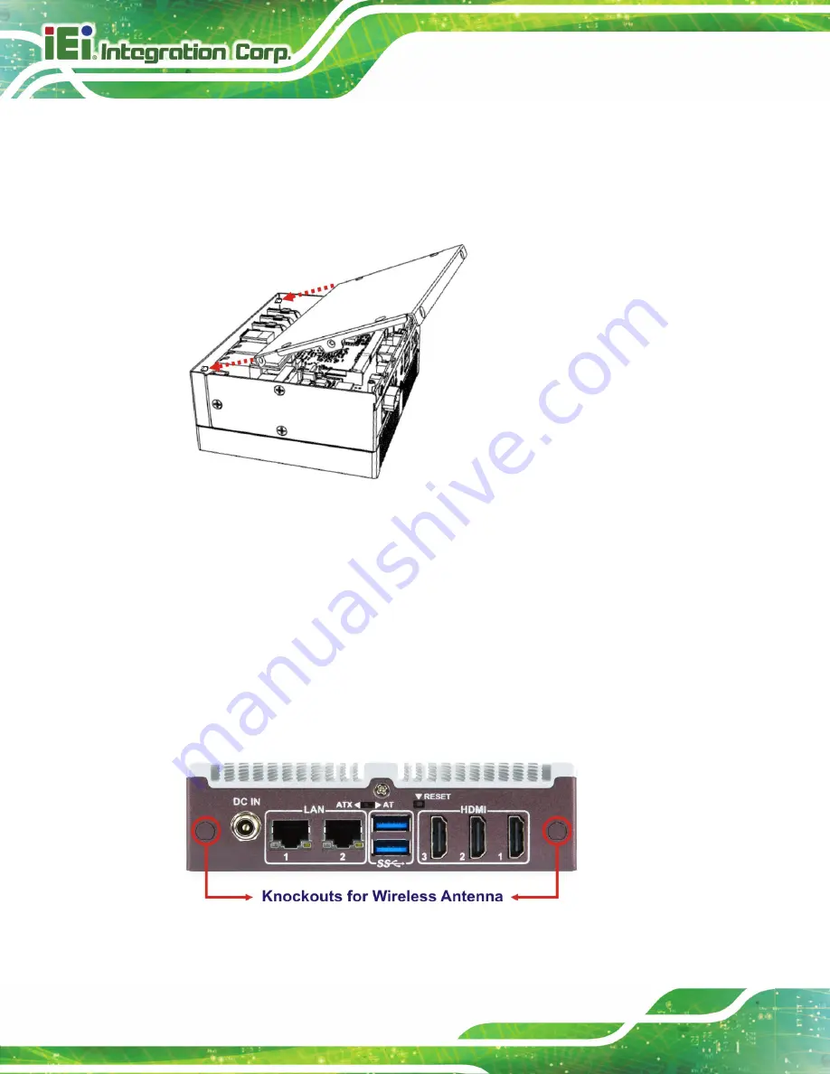
To re-install the bottom surface, insert the two screw holes in the bottom surface into the
two studs inside the chassis first, so that the bottom surface can be positioned correctly
and installed easily.
Figure 3-3: Bottom Surface Installation
3.4 Wireless LAN Module Installation (Optional)
To install the optional wireless LAN (WLAN) module, please follow the steps below.
Step 1:
Remove the bottom surface. See
Section 3.3
Step 2:
Remove the two knockouts for antenna installation. The two knockouts are
located on the rear panel of the IDS-310-AL as shown in
Figure 3-4: Knockouts for Wireless Antenna
Summary of Contents for IDS-310-AL
Page 15: ...IDS 310 AL Embedded System Page 1 Chapter 1 1 Introduction...
Page 23: ...IDS 310 AL Embedded System Page 9 Chapter 2 2 Unpacking...
Page 26: ...IDS 310 AL Embedded System Page 12 Chapter 3 3 Installation...
Page 37: ...IDS 310 AL Embedded System Page 23 Figure 3 16 Hook Onto Mounting Bracket...
Page 47: ...IDS 310 AL Embedded System Page 33 Chapter 4 4 BIOS...
Page 81: ...IDS 310 AL Embedded System Page 67 Chapter 5 5 Maintenance...
Page 85: ...IDS 310 AL Embedded System Page 71 Chapter 6 6 Interface Connectors...
Page 93: ...IDS 310 AL Embedded System Page 79 Appendix A A Regulatory Compliance...
Page 98: ...IDS 310 AL Embedded System Page 84 Appendix B B Safety Precautions...
Page 104: ...IDS 310 AL Embedded System Page 90 Appendix C C BIOS Menu Options...
Page 107: ...IDS 310 AL Embedded System Page 93 Appendix D D Watchdog Timer...
Page 110: ...IDS 310 AL Embedded System Page 96 Appendix E E Error Beep Code...
Page 112: ...IDS 310 AL Embedded System Page 98 Appendix F F Hazardous Materials Disclosure...


