


ICECARE-05 Pocket Mobile Field Assistant
Page 50
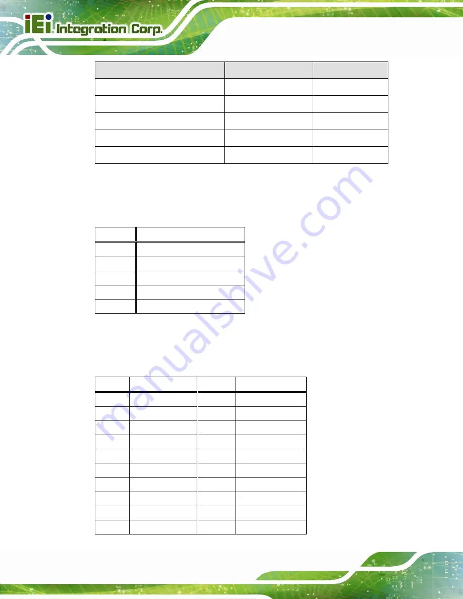
Connector
Type
Label
LCD connector
40-pin wafer
CN3
RFID/UHF connector
12-pin wafer
CN4
Speaker connector
2-pin wafer
J2
Touch panel connector
8-pin wafer
J6
Wi-Fi antenna connectors
Antenna connector
CN2, CN5
Table 5-1: Peripheral Interface Connectors
5.2.1 Battery Connector (J3)
PIN NO.
DESCRIPTION
1 BATT
2 SCL
3 SDA
4 CHG_TS
5 GND
Table 5-2: Battery Connector (J3) Pinouts
5.2.2 Camera Connector (J5)
PIN NO.
DESCRIPTION
PIN NO.
DESCRIPTION
1 GND
13 CAM_D2
2 AFVDD_2.8V 14 CAM_RST
3 FREX
15 CAM_HS
4 STROBE
16 CAM_VS
5 GND
17 CAM_PCLK
6 CAM_D9
18 SDA
7 CAM_D8
19 SCL
8 CAM_D7
20 CHIP_EN#
9
CAM_D6
21
CAM_MCLK
10
CAM_D5
22
NC
Summary of Contents for ICECARE-05-ET-R10
Page 10: ...ICECARE 05 Pocket Mobile Field Assistant Page 1 Chapter 1 1 Introduction...
Page 18: ...ICECARE 05 Pocket Mobile Field Assistant Page 9 Chapter 2 2 Unpacking...
Page 21: ...ICECARE 05 Pocket Mobile Field Assistant Page 12 Chapter 3 3 Installation...
Page 28: ...ICECARE 05 Pocket Mobile Field Assistant Page 19 Chapter 4 4 Using the ICECARE 05...
Page 56: ...ICECARE 05 Pocket Mobile Field Assistant Page 47 Chapter 5 5 Interface Connectors...
Page 65: ...ICECARE 05 Pocket Mobile Field Assistant Page 56 Appendix A A Safety Precautions...
Page 70: ...ICECARE 05 Pocket Mobile Field Assistant Page 61 Appendix B B Hazardous Materials Disclosure...


