background image


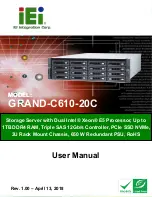
GRAND-C610-20C 


Page iv 

Manual Conventions 


WARNING 

Warnings appear where overlooked details may cause damage to the 

equipment or result in personal injury. Warnings should be taken 

seriously. 


CAUTION 

Cautionary messages should be heeded to help reduce the chance of 

losing data or damaging the product.   


NOTE 

These messages inform the reader of essential but non-critical 

information. These messages should be read carefully as any directions 

or instructions contained therein can help avoid making mistakes. 


HOT SURFACE 

This symbol indicates a hot surface that should not be touched without 

taking care. 


Summary of Contents for GRAND-C610-20C

Page 1: ...rage Server with Dual Intel Xeon E5 Processor Up to 1TB DDR4 RAM Triple SAS 12Gb s Controller PCIe SSD NVMe 3U Rack Mount Chassis 650 W Redundant PSU RoHS GRAND C610 20C Industrial server MODEL MODEL...

Page 2: ...GRAND C610 20C Page ii Revision Date Version Changes April 13 2018 1 00 Initial release...

Page 3: ...ising out of the use or inability to use the product or documentation even if advised of the possibility of such damages This document contains proprietary information protected by copyright All right...

Page 4: ...autionary messages should be heeded to help reduce the chance of losing data or damaging the product NOTE These messages inform the reader of essential but non critical information These messages shou...

Page 5: ...ECAUTIONS 12 3 2 1 High Surface Temperature 13 3 3 INSTALLATION PROCEDURE 14 3 4 MEMORY MODULE INSTALLATION 14 3 5 NETWORK EXPANSION CARD INSTALLATION 17 3 6 HARD DRIVE INSTALLATION 19 3 6 1 Front Pan...

Page 6: ...TERFACE PANEL CONNECTORS 39 5 2 1 Ethernet and USB 3 0 Combo Connectors 39 5 2 2 IPMI LAN Port Connector 40 5 2 3 IPMI VGA Connector 40 5 2 4 IPMI Console DB 9 Connector 40 5 2 5 Audio Jack 41 5 2 6 E...

Page 7: ...el 20 Figure 3 3 HDD Tray Removal Front Panel 21 Figure 3 4 HDD Tray Installation 21 Figure 3 5 HDD Installation Front Panel 22 Figure 3 6 Release Drive Tray Rear Panel 22 Figure 3 7 Drive Tray Instal...

Page 8: ...ard Slot M2_SATA1 Pinouts 38 Table 5 5 SATA Connector SATA1 Pinouts 38 Table 5 6 PCIe Power Connector CON5 CON6 Pinouts 38 Table 5 7 Power and Reset Button Connector SW1 Pinouts 39 Table 5 8 Ethernet...

Page 9: ...GRAND C610 20C Page 1 Chapter 1 1 Introduction...

Page 10: ...SAS for connectivity with up to 16 HDDs and 4 SSDs ensuring each controller can fully utilize the maximum bandwidth to optimize performance and reliability The GRAND C610 20C supports network expansio...

Page 11: ...dicators 1 Power button 7 IPMI VGA 2 LED Indicator 10 GbE status LAN storage expansion port status 8 Two Gigabit LAN ports Left LAN1 Right LAN2 3 EC GPIO 9 Four USB 3 0 ports 4 Audio jack mic in and l...

Page 12: ...ashes of orange The system is in sleep mode Off All the hard drives are in standby mode LAN Orange Orange The disk data is being accessed from the network and a read write error occurs during the proc...

Page 13: ...eon Processor E5 2623 v3 4 core 10M Cache 3 00 GHz Intel Xeon Processor E5 2620 v3 6 core 15M Cache 2 40 GHz Intel Xeon Processor E5 2630 v3 8 core 20M Cache 2 40 GHz Intel Xeon Processor E5 2640 v3 8...

Page 14: ...nsions 130 8 mm H x 444 mm W x 744 D mm Weight Net system only 22 42 kg 49 43 lb Gross with packing and accessories 30 19 kg 66 56 lb Sound Level Sound pressure LpAm 37 8 dB A Power Consumption Sleep...

Page 15: ...GRAND C610 20C Page 7 Chapter 2 2 Unpacking...

Page 16: ...vendor the GRAND C610 20C was purchased from or contact an IEI sales representative directly by sending an email to sales ieiworld com The GRAND C610 20C is shipped with the following components Quant...

Page 17: ...0GbE QSFP network expansion card P N LAN 40G2SF MLX Dual port 10GbE SFP network expansion card P N LAN 10G2SF MLX Dual port 10GBASE T network expansion card P N LAN 10G2T X550 USB 3 1 Gen 2 10Gbps Typ...

Page 18: ...GRAND C610 20C Page 10 Item and Part Number Image MiniSAS cable SFF 8644 to SFF 8644 1 0 m P N CAB SAS10M 8644 MiniSAS cable SFF 8644 to SFF 8644 0 5m P N CAB SAS05M 8644 Table 2 2 Optional Items...

Page 19: ...GRAND C610 20C Page 11 Chapter 3 3 Installation...

Page 20: ...g Before handling the board touch any grounded conducting material During the time the board is handled frequently touch any conducting materials that are connected to the ground Use an anti static pa...

Page 21: ...per the electrical values indicated on the label attached to the back of the GRAND C610 20C 3 2 1 High Surface Temperature WARNING Some surfaces of the equipment may become hot during operation The s...

Page 22: ...HDD Step 4 Mount the GRAND C610 20C Step 5 Connect peripheral devices Step 6 Power the system up 3 4 Memory Module Installation The GRAND C610 20C has 16 memory slots and supports DDR4 RDIMMs and LRDI...

Page 23: ...re installed use P0 A0 P0 B0 P0 C0 P0 D0 P1 A0 P1 B0 P1 C0 and P1 D0 When 12 memory modules are installed use P0 A0 P0 B0 P0 C0 P0 D0 P0 A1 P0 C1 P1 A0 P1 B0 P1 C0 P1 D0 P1 A1 and P1 C1 To install a m...

Page 24: ...lips gently by pulling them out of the sides of the RAM slot Step 6 Grasp the edge of the RAM module Align the notch on the gold edge of the RAM module with the notch in the RAM slot Insert the RAM mo...

Page 25: ...slots for network expansion Insert an extra network expansion card optional purchase to the motherboard of the GRAND C610 20C to increase the network bandwidth Step 1 Turn off the GRAND C610 20C Disc...

Page 26: ...GRAND C610 20C Page 18 Step 4 Hold the handle pulled backwards to remove the Motherboard Drawer Step 5 Loosen the screw and remove the expansion slot cover...

Page 27: ...urther Then fasten the screw Step 7 Push back the Motherboard Drawer Then fasten the screw Step 8 Connect the power adaptor and cables to the GRAND C610 20C 3 6 Hard Drive Installation NOTE Before ins...

Page 28: ...slots for installing 2 5 3 5 SATA HDD SSD To install the hard drive into the system please follow the steps below Step 1 Unlock the latch and press the button to release the HDD tray as shown in Figu...

Page 29: ...Attach the drive to the tray and secure the four screws in the bottom sides of the drive tray Figure 3 4 Figure 3 4 HDD Tray Installation Step 4 Insert the drive tray into the GRAND C610 20C all the w...

Page 30: ...D Sequence shown above 3 6 2 Rear Panel The rear panel of the GRAND C610 20C has 4 drive slots for installing 2 5 SATA SSD To install the hard drive into the system please follow the steps below Step...

Page 31: ...ure 3 7 Figure 3 7 Drive Tray Installation Step 4 Insert the drive tray into the GRAND C610 20C all the way to the end Slide the latch to secure the drive tray See Figure 3 8 Figure 3 8 HDD Installati...

Page 32: ...improper installation of hard disks in any occasions for any reasons CAUTION The following items are not recommended for use with this product Brand Model Rank Family Type HDD Firmware Capacity Seagat...

Page 33: ...ing standards Before purchasing the server racks please make sure the server racks conform to the following criteria Rack size Mounting post width 451mm Panel width 485mm Mounting post depth 579 1mm 8...

Page 34: ...tem Incorrect voltages applied to the system may cause damage to the internal electronic components and may also cause injury to the user To power on the GRAND C610 20C please make sure of the followi...

Page 35: ...igure 3 9 Power Connection Step 2 Push the power button Figure 3 10 Figure 3 10 Power Button Step 3 To turn off the GRAND C610 20C press the power button for 1 5 seconds To force turn off press the po...

Page 36: ...GRAND C610 20C Page 28 Chapter 4 4 Maintenance...

Page 37: ...etails on anti static precautions please refer to Section 3 1 4 1 Component Replacement Procedure WARNING Users are not advised to attempt to repair or replace any internal or external components of t...

Page 38: ...ly unit please follow the steps below Step 1 Turn off the GRAND C610 20C Disconnect the power adaptor network cable s and any other connectors or cables from the GRAND C610 20C Step 2 Hold the black h...

Page 39: ...power adaptor and cables to the GRAND C610 20C 4 3 Fan Module Replacement WARNING Replace the fan module within 3 minutes to avoid overheating the system Do not attempt to operate the system without t...

Page 40: ...GRAND C610 20C Page 32 Step 2 Remove the fan module by grasping and pulling up the fan module from the fan slot Step 3 Insert the fan module into the fan slot until the fan module is fully seated...

Page 41: ...GRAND C610 20C Page 33 Chapter 5 5 Interface Connectors...

Page 42: ...ral interface connectors The connector locations are shown in Figure 5 1 The connector pinouts for these connectors are listed in the following sections Figure 5 1 Jumper and Connector Locations 5 1 1...

Page 43: ...19 GND 8 N C 20 N C 9 5VSB 21 N C 10 12V 22 N C 11 12V 23 N C 12 N C 24 GND Table 5 2 ATX Power Connector ATX1 Pinouts 5 1 3 M 2 PCIe Card Slot M2_PCIE1 PIN NO DESCRIPTION PIN NO DESCRIPTION 1 GND 2 3...

Page 44: ...5 GND 46 N C 47 PERn0 48 N C 49 PERp0 50 PERST I 0 3 3V 51 GND 52 CLKREQ I O 0 3 3V 53 REFCLKN 54 PEWake IO 0 3 3V 55 REFCLKP 56 Reserved MFG Data 57 GND 58 Reserved MFG Clock 59 Module Key 60 Module...

Page 45: ...3V 15 GND 16 3 3V 17 N C 18 3 3V 19 N C 20 N C 21 GND 22 N C 23 N C 24 N C 25 N C 26 N C 27 GND 28 N C 29 N C 30 N C 31 N C 32 N C 33 GND 34 N C 35 N C 36 N C 37 N C 38 DEVSLP I 0 3 3V 39 GND 40 N C 4...

Page 46: ...3 3V 75 GND Table 5 4 M 2 SATA Card Slot M2_SATA1 Pinouts 5 1 5 SATA Connector SATA1 PIN NO DESCRIPTION PIN NO DESCRIPTION 1 GND 5 SATA_RX 2 SATA_TX 6 SATA_TX 3 SATA_TX 7 SATA2_DOM_5V 4 GND 8 N C Tab...

Page 47: ...ors can be found in the following sections 5 2 1 Ethernet and USB 3 0 Combo Connectors PIN NO DESCRIPTION PIN NO DESCRIPTION 1 MDI0 5 MDI2 2 MDI0 6 MDI2 3 MDI1 7 MDI3 4 MDI1 8 MDI3 Table 5 8 Ethernet...

Page 48: ...Port Connector Pinouts 5 2 3 IPMI VGA Connector PIN NO DESCRIPTION PIN NO DESCRIPTION 1 Red 2 Green 3 Blue 4 NC 5 GND 6 GND 7 GND 8 GND 9 VGAVCC 10 GND 11 NC 12 DDCDA 13 HSYNC 14 VSYNC 15 DDCCLK Tabl...

Page 49: ...n Table 5 13 Audio Jack 5 2 6 EC GPIO PIN NO DESCRIPTION 1 GND 2 EC KSO16 SMOSI GPC3 3 GND 4 GND Table 5 14 EC GPIO Pinouts 5 2 7 SAS Connector PIN NO DESCRIPTION PIN NO DESCRIPTION S1 GND P1 NC S2 BP...

Page 50: ...PIN NO DESCRIPTION PIN NO DESCRIPTION S7 GND P7 5V_HDD S8 GND P8 5V_HDD S9 NC P9 5V_HDD S10 NC P10 GND S11 GND P11 HDD1_LED_ACT S12 NC P12 GND S13 NC P13 12V_PS S14 GND P14 12V_PS P15 12V_PS Table 5 1...

Page 51: ...GRAND C610 20C Page 43 Appendix A A Regulatory Compliance...

Page 52: ...requirements and other relevant provisions of Directive 1999 5 EC Bulgarian IEI Integration Corp 1999 5 esky Czech IEI Integration Corp t mto prohla uje e tento za zen je ve shod se z kladn mi po adav...

Page 53: ...tuvi Lithuanian IEI Integration Corp deklaruoja kad is ranga atitinka esminius reikalavimus ir kitas 1999 5 EB Direktyvos nuostatas Nederlands Dutch IEI Integration Corp dat het toestel toestel in ove...

Page 54: ...direktive 1999 5 ES Slovensky Slovak IEI Integration Corp t mto vyhlasuje e zariadenia sp a z kladn po iadavky a v etky pr slu n ustanovenia Smernice 1999 5 ES Suomi Finnish IEI Integration Corp vaku...

Page 55: ...ence at his own expense Federal Communication Commission Interference Statement This equipment has been assembled with components that comply with the limits for a Class B digital device pursuant to P...

Page 56: ...GRAND C610 20C Page 48 Appendix B B Safety Precautions...

Page 57: ...0 20C is opened Make sure the power is turned off and the power cord is disconnected whenever the GRAND C610 20C is being installed moved or modified Do not apply voltage levels that exceed the specif...

Page 58: ...ollowing anti static precautions are strictly adhered to Wear an anti static wristband Wearing a simple anti static wristband can help to prevent ESD from damaging any electrical component Self ground...

Page 59: ...electronic products carrying the mark left must be disposed of separately from normal household waste This includes monitors and electrical accessories such as signal cables or power cords When you ne...

Page 60: ...explicitly mentioned in the cleaning tips Below is a list of items to use when cleaning the GRAND C610 20C Cloth Although paper towels or tissues can be used a soft clean piece of cloth is recommended...

Page 61: ...GRAND C610 20C Page 53 Appendix C C Hazardous Materials Disclosure...

Page 62: ...hese components will be separately marked Please refer to the following table Part Name Toxic or Hazardous Substances and Elements Lead Pb Mercury Hg Cadmium Cd Hexavalent Chromium CR VI Polybrominate...

Page 63: ...20C Page 55 RoHS RoHS Pb Hg Cd CR VI PBB PBDE O O O O O O O O O O O O O O O O O O O O O O O O O O O O O O O O O O O O O O O O O O O O O O O O O SJ T 11363 2006 GB T 26572 2011 X SJ T 11363 2006 GB T...

Reviews: