


DM-F Series Monitor
Page 71
5.4 Change the Touchscreen Interface
If the touchscreen interface must be changed from a USB interface to an RS-232 interface
or from an RS-232 interface to a USB interface, the following steps must be followed.
Step 1:
Uninstall the touchscreen driver
Step 2:
Remove the interface cable i.e. remove the USB cable or the RS-232 cable
Step 3:
Install the new cable i.e. install the RS-232 cable or the USB cable.
Step 4:
Reinstall the driver CD as described above.
Step 0:
5.5 Calibrating the Touchscreen
To calibrate the touchscreen cursor with the motion of the touch pen (or finger), please
follow the steps below:
Step 1:
Make sure the system is properly connected through a USB or an RS-232
interface to the DM-F series monitor.
Step 2:
Make sure the touchscreen driver is properly installed.
Step 3:
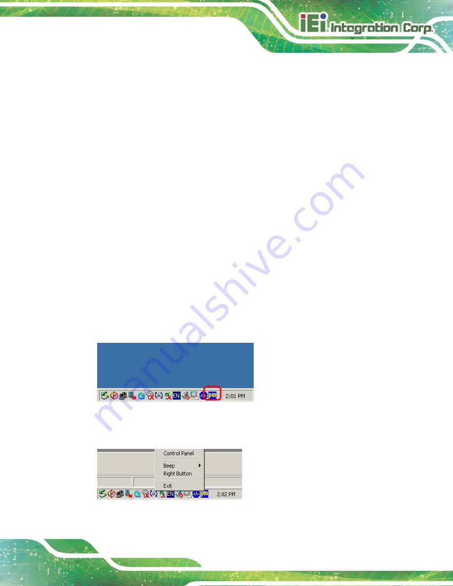
Locate the PenMount Monitor icon in the bottom right corner of the screen.
Figure 5-6: PenMount Monitor Icon
Step 4:
Click the icon. A pop up menu appears. See
Figure 5-7: PenMount Monitor Popup Menu
Summary of Contents for DM-F SERIES
Page 16: ......
Page 17: ...DM F Series Monitor Page 1 Chapter 1 1 Introduction ...
Page 38: ...DM F Series Monitor Page 22 Chapter 2 2 Unpacking ...
Page 42: ...DM F Series Monitor Page 26 Chapter 3 3 Installation ...
Page 69: ...DM F Series Monitor Page 53 Figure 3 45 Monitor Arm Mounting ...
Page 70: ...DM F Series Monitor Page 54 Chapter 4 4 On Screen Display OSD Controls ...
Page 80: ...DM F Series Monitor Page 64 Chapter 5 5 Software Drivers ...
Page 90: ...DM F Series Monitor Page 74 Chapter 6 6 AD Boards ...
Page 102: ...DM F Series Monitor Page 86 Appendix A A Regulatory Compliance ...
Page 104: ...DM F Series Monitor Page 88 Appendix B B Safety Precautions ...
Page 110: ...DM F Series Monitor Page 94 Appendix C C smartOSD ...
Page 117: ...DM F Series Monitor Page 101 C 4 1 Manage Page Figure C 6 Manage Page ...
Page 118: ...DM F Series Monitor Page 102 C 4 2 EDID Page Figure C 7 EDID Page ...
Page 119: ...DM F Series Monitor Page 103 C 4 3 Image Page Figure C 8 Image Page ...
Page 120: ...DM F Series Monitor Page 104 C 4 4 Display Page for analog signal Figure C 9 Display Page ...
Page 121: ...DM F Series Monitor Page 105 C 4 5 Color Page Figure C 10 Color Page ...
Page 124: ...DM F Series Monitor Page 108 C 4 8 About Page Figure C 13 About Page ...
Page 128: ...DM F Series Monitor Page 112 Appendix D D Hazardous Materials Disclosure ...


