IEI Technology DM-F SERIES User Manual Download Page 127


DM-F Series Monitor


Page 111 

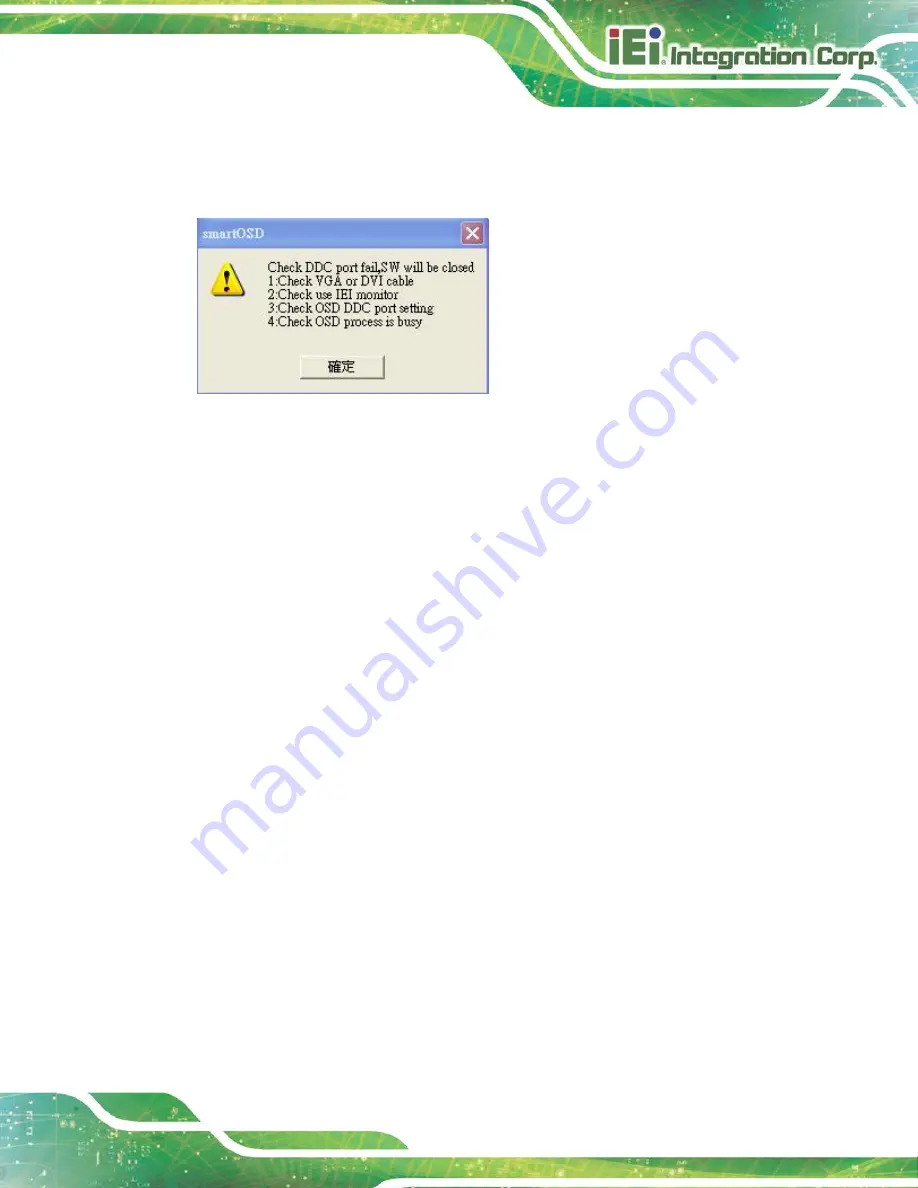
C.5.4 DDC Port Failure 

The DDC port fail error message shown below appears. 


Figure C-18: DDC Port Failure 

Solutions: 


Check VGA or HDMI cable 


Check an IEI monitor is being used 


Make sure the version is version 2.3 for the AFOLUX/MDM series and version 

1.5 for the DM/ISDM/TDM/SRM/LCD-KIT series that have the SmartOSD 

functions 


Check if the OSD control status is busy. A busy signal may cause the signal 

message for a short time. 


Summary of Contents for DM-F SERIES

Page 1: ...DM F Series Monitor Page I User Manual DM Series Industrial Monitor MODEL DM F series 6 5 23 8 LCD Monitor DisplayPort HDMI VGA IP 65 Protection RoHS Rev 2 01 February 24 2021 ...

Page 2: ...Model Variations Updated Section 1 7 2 DM F12A DM F19A Connectors Updated Section 1 8 Technical Specifications Updated Section 1 9 3 DM F19A Physical Dimensions Modified Section 3 3 1 Panel Mounting Modified Section 3 3 2 Cabinet and Rack Installation January 21 2016 1 14 Added 6 5 8 and 19 model information August 6 2015 1 13 Added Section 3 2 8 1 Installing RS 232 Connector April 29 2015 1 12 Up...

Page 3: ...erate it in an area that exceeds the maximum operating temperature described in the user manual Vorsicht Um eine Überhitzung des Systems zu vermeiden betreiben Sie es ausschließlich im zulässigen Betriebstemperaturbereich Dieser ist in der Bedienungsanleitung vermerkt Attention Pour éviter la surchauffe du système ne l utilisez pas dans une zone dont la température dépasse les limites décrits dans...

Page 4: ...ferimento al manuale utente per le specifiche sull alimentazione Atención Utilice solamente el adaptador de corriente alterna CA con Marcas Conformidad otorgadas Cualquier otro adaptador no otorgado aumenta el riesgo de explosión o incendio Por favor consulte el manual del usuario para las especificaciones del adaptador de alimentación 警告 只能使用經過認證 適用於本系統的電源變壓器與電源線 使用不適用的電 源變壓器將可能導致火災或爆炸 電源變壓器規格請參考...

Page 5: ...arising out of the use or inability to use the product or documentation even if advised of the possibility of such damages This document contains proprietary information protected by copyright All rights are reserved No part of this manual may be reproduced by any mechanical electronic or other means in any form without prior written permission of the manufacturer TRADEMARKS All registered tradema...

Page 6: ...N Cautionary messages should be heeded to help reduce the chance of losing data or damaging the product NOTE These messages inform the reader of essential but non critical information These messages should be read carefully as any directions or instructions contained therein can help avoid making mistakes HOT SURFACE This symbol indicates a hot surface that should not be touched without taking car...

Page 7: ... F W 15A Specifications 8 1 8 1 DM F17A DM F24A Specifications 10 1 9 PHYSICAL DIMENSIONS 12 1 9 1 DM F65A Physical Dimensions 12 1 9 2 DM F08A Physical Dimensions 13 1 9 3 DM F12A Physical Dimensions 14 1 9 4 DM F15A Physical Dimensions 15 1 9 1 DM FW15A Physical Dimensions 16 1 9 2 DM F17A Physical Dimensions 17 1 9 3 DM F19A Physical Dimensions 18 1 9 1 DM FW19A Physical Dimensions 19 1 9 2 DM ...

Page 8: ...rved for Resistive Touch 32 3 2 8 1 Installing RS 232 Connector 33 3 3 MOUNTING THE MONITOR 35 3 3 1 Panel Mounting 35 3 3 2 Cabinet and Rack Installation for F65A F17A FW19A 44 3 3 3 Cabinet and Rack Installation for F19A 47 3 3 4 Wall Mounting 49 3 3 5 Stand Installation 51 3 3 6 Arm Installation 52 4 ON SCREEN DISPLAY OSD CONTROLS 54 4 1 OSD KEYPAD 55 4 2 OSD MENU STRUCTURE 57 4 3 USING THE OSD...

Page 9: ...mper JP2 79 6 2 10 EIDE Firmware Update Jumper JP3 79 6 3 AV 60381 AD BOARD 80 6 3 1 AV 60381 Peripheral Interface Connectors 80 6 3 2 Backlight Inverter Connector INVERTER1 81 6 3 3 LVDS Connector LVDS1 82 6 3 4 OSD Keypad Connector KEYPAD1 82 6 3 5 Power Input Connector PWR2 83 6 3 6 RS 232 Connector for Touchscreen RS232_1 83 6 3 7 USB Connector for Touchscreen USB_TOUCH1 83 6 3 8 Touchscreen C...

Page 10: ...ARTOSD INSTALLATION 95 C 4 SOFTWARE ILLUSTRATION 98 C 4 1 Manage Page 101 C 4 2 EDID Page 102 C 4 3 Image Page 103 C 4 4 Display Page for analog signal 104 C 4 5 Color Page 105 C 4 6 PIP Page 106 C 4 7 System Page 107 C 4 8 About Page 108 C 5 SMARTOSD FAQ 109 C 5 1 Windows 2000 Installation Failure 109 C 5 2 Vista Installation Failure 109 C 5 3 Model Failure 110 C 5 4 DDC Port Failure 111 D HAZARD...

Page 11: ...ensions Unit mm 14 Figure 1 13 DM F15A Physical Dimensions Unit mm 15 Figure 1 14 DM FW15A Physical Dimensions Unit mm 16 Figure 1 15 DM F17A Physical Dimensions Unit mm 17 Figure 1 16 DM F19A Physical Dimensions Unit mm 18 Figure 1 17 DM FW19A Physical Dimensions Unit mm 19 Figure 1 18 DM F22A Physical Dimensions Unit mm 20 Figure 1 19 DM F24A Physical Dimensions Unit mm 21 Figure 3 1 DC Jack 28 ...

Page 12: ...the Panel 41 Figure 3 27 Panel Mounting Clamp Installation 42 Figure 3 28 Mounting Clamps Holder Dimensions 42 Figure 3 29 Ultra Set Plate Dimensions 43 Figure 3 30 Bolt Dimensions 43 Figure 3 31 Steering Button Dimensions 43 Figure 3 32 Secure the Mounting Clamp Holders 45 Figure 3 33 Slide into the Rack Cabinet Bracket 45 Figure 3 34 Secure the Rack Cabinet Bracket 46 Figure 3 35 Install into a ...

Page 13: ...Figure 5 1 Welcome Screen 68 Figure 5 2 License Agreement 69 Figure 5 3 Initiate Install 69 Figure 5 4 Installation Starts 70 Figure 5 5 Finish Installation 70 Figure 5 6 PenMount Monitor Icon 71 Figure 5 7 PenMount Monitor Popup Menu 71 Figure 5 8 Configuration Screen 72 Figure 5 9 Calibration Initiation Screen 73 Figure 5 10 Calibration Screen 73 Figure 6 1 AV 6038 AD Board Layout Diagram 75 Fig...

Page 14: ...ectors 76 Table 6 2 Backlight Inverter Connector INVERTER1 Pinouts 77 Table 6 3 LVDS Connector LVDS1 Pinouts 77 Table 6 4 OSD Keypad Connector CN14 Pinouts 78 Table 6 5 Power Input Connector CN9 Pinouts 78 Table 6 6 RS 232 Connector for Touchscreen RS232_1 Pinouts 78 Table 6 7 USB Connector for Touchscreen USB_TOUCH1 Pinouts 79 Table 6 8 Touchscreen Connector J1 Pinouts 79 Table 6 9 LVDS Panel Vol...

Page 15: ... Connector VGA2 Pinouts 84 Table 6 20 Backlight Voltage Select Jumper JP5 Pinouts 84 Table 6 21 LVDS Panel Voltage Select Jumper JP2 Pinouts 84 Table 6 22 Power Input Setting Jumper JP4 Pinouts 85 Table 6 23 Touchscreen Type Select Jumper JP1 Pinouts 85 Table C 1 SmartOSD Menu Structure 100 ...

Page 16: ......

Page 17: ...DM F Series Monitor Page 1 Chapter 1 1 Introduction ...

Page 18: ...ront panel provides IP 65 protection which effectively wards off dust and water Flexible analog or digital interfaces are provided for ease of connection with a management computer 1 2 Features The DM F series have the following standard features Robust IP 65 aluminum front bezel Aesthetic ultra thin bezel for seamless panel mount installation Wide range DC input 9 V 36 V or 12 V Flexible video in...

Page 19: ... Capacitive 9 36 V Yes HDMI Yes DM FW19A PC 18 5 Capacitive 9 36 V Yes HDMI Yes DM F19A R 19 Resistive 9 36 V Yes DVI D Yes DM F19A PC Capacitive 9 36 V Yes DVI D Yes DM F22A PC 21 5 Capacitive 9 36 V Yes HDMI Yes DM F24A PC 23 8 Capacitive 9 36 V Yes HDMI Yes Table 1 1 DM F Series Model Variations 1 4 Applications The DM F series LCD monitor is designed for rigorous industrial environments where ...

Page 20: ...ll service receptionist kiosk o Hospital self registration terminal o Interactive photo kiosk o Video rental kiosk o Self service POS terminal 1 5 Front View The front of the DM F series LCD monitor is a flat panel LCD screen surrounded by an aluminum frame Figure 1 2 shows a typical monitor front view Figure 1 2 Typical Monitor Front View ...

Page 21: ...to retention screw holes that support VESA mounting A 5 key 7 key membrane OSD keypad is also located on the rear panel The following diagrams show the rear panel of the DM F series Figure 1 3 DM F65A 08A Rear View Figure 1 4 DM F12A 15A W15A 17A 19A W19A 22A 24A Rear View ...

Page 22: ...llowing sections show the I O interfaces of the DM F series LCD monitor All connectors are fully described in Section 3 2 1 7 1 DM F65A and DM F08A Connectors Figure 1 5 Bottom Panel Connectors DM F65A 08A Figure 1 6 Side Panel Connectors DM F65A 08A ...

Page 23: ...7 2 DM F12A DM F19A Connectors Figure 1 7 Bottom Panel Connectors DM F12A 15A W15A 17A 19A W19A Figure 1 8 Side Panel Connector DM F12A 15A 17A 19A 1 7 3 DM F22A and DM F24A Connectors Figure 1 9 Bottom Panel Connectors DM F22A 24A ...

Page 24: ...50 000 70 000 50 000 Touchscreen 5 wire resistive type 5 wire resistive type or projected capacitive type DM FW15A P CAP only Touch Controller Penmount 6000 Resistive type Penmount 6000 Projected capacitive type EETI EXC31xx series AD Board AV 60381 AV 6038 OSD Button 5 key 5 key 7 key 7 key 7 key Smart OSD Yes Yes Yes Yes Yes Dimensions mm W x H x D 191 8 x 154 36 x 42 88 222 2 x 182 2 x 42 7 322...

Page 25: ...non condensing I O Ports 1 x VGA 1 x DVI 1 x USB 2 0 for touch 1 x VGA 1 x HDMI 1 x DisplayPort 1 1 1 x USB 2 0 for touch Reserved Ports 1 x RS 232 for resistive touch Power 1 x Lockable DC in jack 12 V Optional 9V 36V power input terminal block 1 x Lockable DC in jack 9 V 36 V 1 x Power input terminal block 9 V 36 V Power Consumption 12V 0 5A 12V 0 5A 9V 2 2A 36V 0 5A 9V 1 6A 36V 0 4A 9V 1 3A 36V...

Page 26: ...e Penmount 6000 Projected capacitive type EETI EXC31xx series EETI EXC31xx series AD Board AV 6038 AV 6038 AV 6038 AV 6038 AV 6038 OSD Button 7 key 7 key 7 key 7 key 7 key Smart OSD Yes Yes Yes Yes Yes Dimensions mm W x H x D 408 4 x 341 4 x 49 3 468 8 x 288 2 x 48 9 447 4 x 372 4 x 49 6 550 4 x 358 4 x 49 1 600 x 382 x 49 4 Cutout Dimensions W x H mm 391 x 324 447 8 x 267 2 430 x 355 532 x 340 57...

Page 27: ... touch 1 x VGA 1 x DP 1 1 1 x DVI 1 x USB 2 0 for touch 1 x VGA 1 x HDMI 1 x DisplayPort 1 1 1 x USB 2 0 for touch Reserved Ports 1 x RS 232 for resistive touch N A Power 1 x Lockable DC in jack 9 V 36 V 1 x Power input terminal block 9 V 36 V Power Consumption 9V 2 6A 36V 0 6A 9V 1 3A 36V 0 4A 9V 3 3A 36V 0 8A 9V 2 5A 36V 0 6A 9V 3 4A 36V 0 8A IP Level IP 65 compliant front panel Safety EMC CE FC...

Page 28: ...ns The following sections describe the physical dimensions for each model of the DM F series LCD monitor 1 9 1 DM F65A Physical Dimensions The physical dimensions of the DM F65A are shown in Figure 1 12 Figure 1 10 DM F65A Physical Dimensions Unit mm ...

Page 29: ...DM F Series Monitor Page 13 1 9 2 DM F08A Physical Dimensions The physical dimensions of the DM F08A are shown in Figure 1 12 Figure 1 11 DM F08A Physical Dimensions Unit mm ...

Page 30: ...DM F Series Monitor Page 14 1 9 3 DM F12A Physical Dimensions The physical dimensions of the DM F12A are shown in Figure 1 12 Figure 1 12 DM F12A Physical Dimensions Unit mm ...

Page 31: ...DM F Series Monitor Page 15 1 9 4 DM F15A Physical Dimensions The physical dimensions of the DM F15A are shown in Figure 1 13 Figure 1 13 DM F15A Physical Dimensions Unit mm ...

Page 32: ...DM F Series Monitor Page 16 1 9 1 DM FW15A Physical Dimensions The physical dimensions of the DM FW15A are shown in Figure 1 13 Figure 1 14 DM FW15A Physical Dimensions Unit mm ...

Page 33: ...DM F Series Monitor Page 17 1 9 2 DM F17A Physical Dimensions The physical dimensions of the DM F17A are shown in Figure 1 15 Figure 1 15 DM F17A Physical Dimensions Unit mm ...

Page 34: ...DM F Series Monitor Page 18 1 9 3 DM F19A Physical Dimensions The physical dimensions of the DM F19A are shown in Figure 1 12 Figure 1 16 DM F19A Physical Dimensions Unit mm ...

Page 35: ...DM F Series Monitor Page 19 1 9 1 DM FW19A Physical Dimensions The physical dimensions of the DM FW19A are shown in Figure 1 12 Figure 1 17 DM FW19A Physical Dimensions Unit mm ...

Page 36: ...DM F Series Monitor Page 20 1 9 2 DM F22A Physical Dimensions The physical dimensions of the DM F22A are shown in Figure 1 18 Figure 1 18 DM F22A Physical Dimensions Unit mm ...

Page 37: ...DM F Series Monitor Page 21 1 9 3 DM F24A Physical Dimensions The physical dimensions of the DM F24A are shown in Figure 1 19 Figure 1 19 DM F24A Physical Dimensions Unit mm ...

Page 38: ...DM F Series Monitor Page 22 Chapter 2 2 Unpacking ...

Page 39: ... during the installation process Step 1 Use box cutters a knife or a sharp pair of scissors that seals the top side of the external second box Step 2 Open the external second box Step 3 Use box cutters a knife or a sharp pair of scissors that seals the top side of the internal first box Step 4 Lift the monitor out of the boxes Step 5 Remove both polystyrene ends one from each side Step 6 Pull the ...

Page 40: ...ts Quantity Item Image 1 DM F series 1 USB cable for touchscreen 1 VGA cable 1 Touch pen resistive touch only 1 60W 12V DC adapter with lockable connector 6 5 and 8 models only Table 2 1 Packing List If any of the above items are missing or damaged contact the distributor or sales representative immediately ...

Page 41: ...DM F COMKIT R10 DM F COMKIT R10 N A Power Adapter N A N A 63040 010060 211 RS 63040 010060 211 RS 63040 010060 211 RS DM F17A DM FW19A DM F19A DM F22A DM F24A Arm ARM 31 RS ARM 31 RS ARM 31 RS ARM 31 RS ARM 31 RS Stand STAND C19 R10 STAND A21 R10 STAND C19 R10 STAND A21 R10 STAND C19 R10 STAND A21 R10 STAND C19 R10 STAND A21 R10 STAND C19 R10 STAND A21 R10 Wall Mount Kit WK 190MS R10 WK 190MS R10 ...

Page 42: ...DM F Series Monitor Page 26 Chapter 3 3 Installation ...

Page 43: ...r must be installed and operated only by trained and qualified personnel Maintenance upgrades or repairs may only be carried out by qualified personnel who are familiar with the associated dangers Mounting Since the monitor may weigh up to 8 kg not including a swing arm or other accessories please ensure at least two people assist with mounting the monitor Air Circulation Make sure there is suffic...

Page 44: ...ing sections 3 2 1 DC in Jack The lockable power connector connects to the power adapter and provides power to the monitor Supported power voltage is varied among models as described below DM F65A 08A 12 V DM F12A 15A W15A 17A 19A W19A 22A 24A 9 V 36 V Figure 3 1 DC Jack 3 2 2 9 V 36 V Terminal Block Optional Connect the leads of 9 V 36 V DC power supply into the terminal block Make sure that the ...

Page 45: ...ND Table 3 1 USB Touch Panel Connector Pinouts Figure 3 3 USB Touch Panel Connector 3 2 4 VGA Connector Use the rear panel standard 15 pin female VGA connector to connect the monitor to the system graphics interface PIN DESCRIPTION PIN DESCRIPTION PIN DESCRIPTION 1 RED 6 GROUND 11 NC 2 GREEN 7 GROUND 12 DDCDAT 3 BLUE 8 GROUND 13 HSYNC 4 NC 9 NC 14 VSYNC 5 GROUND 10 GROUND 15 DDCCLK Table 3 2 VGA C...

Page 46: ...VI D connector supports only digital signals PIN DESCRIPTION PIN DESCRIPTION 1 TMDS Data2 13 NC 2 TMDS Data2 14 PVDD1 3 GND 15 GND 4 N C 16 GND 5 N C 17 TMDS Data0 6 DDC Clock SCL 18 TMDS Data0 7 DDC Data SDA 19 GND 8 Analog vertical sync 20 NC 9 TMDS Data1 21 NC 10 TMDS Data1 22 GND 11 GND 23 TMDS Clock 12 NC 24 TMDS Clock Table 3 3 DVI D Connector Pinouts Figure 3 5 DVI D connector ...

Page 47: ...devices such as a TV or computer screen PIN DESCRIPTION PIN DESCRIPTION 1 ML_L3N 2 GND 3 ML_L3P 4 ML_L2N 5 GND 6 ML_L2P 7 ML_L1N 8 GND 9 ML_L1P 10 ML_L0N 11 GND 12 ML_L0P 13 GND 14 GND 15 C_DDI0_DP_AUXP 16 GND 17 C_DDI0_DP_AUXN 18 C_DDI0_DP_HPD 19 GND 20 VCC 21 GND 22 GND 23 GND 24 GND Table 3 4 Display Port Connector Pinouts Figure 3 6 DisplayPort connector ...

Page 48: ...MDS_C_DATA0 10 HDMI_TMDS_C_CLK 11 GND 12 HDMI_TMDS_C_CLK 13 NC 14 NC 15 HDMI_DDC_SCLK 16 HDMI_DDC_SDATA 17 GND 18 5V_HDMI 19 HDMI_HPD Table 3 5 HDMI Connector Pinouts Figure 3 7 HDMI Connector 3 2 8 RS 232 Port for Touch Panel Reserved for Resistive Touch Use the side panel standard RS 232 DB 9 female touch panel connector to connect the monitor to the system graphics interface PIN DESCRIPTION PIN...

Page 49: ... user can purchase the RS 232 Touch Cable Kit DM F COMKIT R10 or DM F COMKIT01 R10 and install the RS 232 connector onto the system Please note that the RS 232 port is only available for the resistive type models of the 6 5 19 monitors Step 1 Remove the rear cover retention screws and lift the rear panel off the monitor Figure 3 9 Rear Panel Retention Screw Removal DM F65A 08A ...

Page 50: ...232 knockout hole on the side panel Step 3 Connect the RS 232 flat cable to the internal RS 232 connector 1x9 pin RS232_1 on the AD board See Figure 3 11 Figure 3 11 Connecting RS 232 Cable Step 4 Insert the D sub 9 connector of the RS 232 flat cable into the hole and secure the connector with two hex jack screws ...

Page 51: ... care to tighten the retention screws or bolts until fully secure but do not over tighten Over tightening the retention screws or bolts may cause them to become stripped rendering them useless 3 3 1 Panel Mounting Each model of the DM F series LCD monitor has a series of mounting slots located on the top side and bottom panels for mounting the monitor to a panel Table 3 7 lists the number of mount...

Page 52: ...D monitor into a panel please follow the steps below Step 1 Select the position on the panel to mount the monitor Step 2 Cut out a section of the panel that corresponds to the rear panel dimensions of the monitor Take care that the panel section that is cut out is smaller than the overall size of the metal frame that surrounds the monitor but just large enough for the rear panel of the monitor to ...

Page 53: ...DM F Series Monitor Page 37 Figure 3 15 DM F65A Cutout Dimensions Unit mm Figure 3 16 DM F08A Cutout Dimensions Unit mm Figure 3 17 DM F12A Cutout Dimensions Unit mm ...

Page 54: ...DM F Series Monitor Page 38 Figure 3 18 DM F15A Cutout Dimensions Unit mm Figure 3 19 DM FW15A Cutout Dimensions Unit mm Figure 3 20 DM F17A Cutout Dimensions Unit mm ...

Page 55: ...DM F Series Monitor Page 39 Figure 3 21 DM F19A Cutout Dimensions Unit mm Figure 3 22 DM FW19A Cutout Dimensions Unit mm Figure 3 23 DM F22A Cutout Dimensions Unit mm ...

Page 56: ...ired to install the clamp holders to the DM F65A and DM F08A monitors for panel rack mounting After sliding the monitor through the panel simply insert the panel mounting clamps into the pre formed holes along the top and side panels of the monitors Then tighten the screws that pass through the panel mounting clamps until the plastic caps at the front of all the screws are firmly secured to the pa...

Page 57: ...ting Clamp Holders Step 4 Slide the monitor through the hole until the aluminum frame is flush against the panel Figure 3 26 Figure 3 26 Slide into the Panel Step 5 Insert the panel mounting clamps into the pre formed holes of the clamp holders Figure 3 27 ...

Page 58: ...nting clamps until the plastic caps at the front of all the screws are firmly secured to the panel Figure 3 27 Figure 3 27 Panel Mounting Clamp Installation The dimensions of the clamp holder and the clamp are shown in the following diagrams Figure 3 28 Mounting Clamps Holder Dimensions ...

Page 59: ...DM F Series Monitor Page 43 Figure 3 29 Ultra Set Plate Dimensions Figure 3 30 Bolt Dimensions Figure 3 31 Steering Button Dimensions ...

Page 60: ...tallation To do this please follow the steps below Step 1 Secure the mounting clamps holders to the corresponding holes on the rear of the monitor Figure 3 32 NOTE For DM F65A and DM F08A It is not required to install the clamp holders to the DM F65A and DM F08A monitors for panel rack mounting After sliding the monitor through the panel simply insert the panel mounting clamps into the pre formed ...

Page 61: ...um frame is flush against the front of the bracket Figure 3 33 Figure 3 33 Slide into the Rack Cabinet Bracket Step 3 Insert the panel mounting clamps into the pre formed holes of the clamp holders Figure 3 34 Step 4 Tighten the screws that pass through the rack mounting clamps until the plastic caps at the front of all the screws are firmly secured to the bracket Figure 3 34 ...

Page 62: ...tached rack cabinet bracket into a rack or cabinet Figure 3 35 Figure 3 35 Install into a Rack Cabinet Step 6 Once the LCD monitor with the attached rack cabinet bracket has been properly inserted into the rack or cabinet secure the front of the rack cabinet bracket to the front of the rack or cabinet Figure 3 35 ...

Page 63: ...inet or rack please follow the steps below Step 1 Slide the rear of the DM F series LCD monitor through the rack cabinet bracket until the aluminum frame is flush against the front of the bracket Figure 3 36 Figure 3 36 Slide DM F19A into the Rack Cabinet Bracket Step 2 Secure the rack cabinet bracket to the monitor To do this secure the 10 mounting brackets to the corresponding screw holes on the...

Page 64: ... rack cabinet bracket into a rack or cabinet Figure 3 38 Figure 3 38 Install DM F19A into a Rack Cabinet Step 4 Once the LCD monitor with the attached rack cabinet bracket has been properly inserted into the rack or cabinet secure the front of the rack cabinet bracket to the front of the rack or cabinet Figure 3 35 ...

Page 65: ...has four holes located on the rear panel for mounting the monitor to a wall To mount the DM F series LCD monitor onto a wall please follow the steps below Step 1 Attach the wall mounting kit to the mounting surface with the included screws Make sure it is attached securely Figure 3 39 Figure 3 39 Attach Wall Mounting Kit to the Wall Step 2 Screw the mounting screws to the mounting holes on the rea...

Page 66: ...3 40 Hook Onto Wall Mounting Kit Step 4 Tighten the top screw on the wall mounting kit to securely hold the DM F series in place After this screw is tightened the DM F series should not be able to move Figure 3 41 Tighten Retention Screw ...

Page 67: ...Video Electronics Standards Association VESA standard mounting holes tapped into the rear panel The standard holes are M4 set at 75 mm x 75 mm or 100 mm x 100 mm apart Figure 3 42 and Figure 3 43 Figure 3 42 VESA Mounting Holes DM F65A 08A Figure 3 43 VESA Mounting Holes DM F12A DM F24A ...

Page 68: ...Monitor Stand Mounting 3 3 6 Arm Installation The DM F series LCD monitor has VESA standard mounting holes tapped into the rear panel The standard holes are M4 set at 75 mm x 75 mm or 100 mm x 100 mm apart Figure 3 42 and Figure 3 43 To mount the DM F series LCD monitor onto a monitor arm please follow the steps below Step 1 Line up the threaded holes on the monitor rear panel with the screw holes...

Page 69: ...DM F Series Monitor Page 53 Figure 3 45 Monitor Arm Mounting ...

Page 70: ...DM F Series Monitor Page 54 Chapter 4 4 On Screen Display OSD Controls ...

Page 71: ...table LCD ON OFF Press this button to turn on or turn off the LCD screen AUTO Press this button to automatically adjust the screen When inside a menu press this button to confirm the selection of the item LEFT Press this button to decrease the value or to scroll up from one selected item to another RIGHT Press this button to increase the value or to scroll down from one selected item to another ME...

Page 72: ...to automatically adjust the screen Menu Press this button to open the OSD window exit the main menu or the current menu Left Press this button to increase the value When inside a menu press this button to enter the submenu or confirm the selection of the item Right Press this button to decrease the value Up Press this button to scroll up from one selected item to another Down Press this button to ...

Page 73: ...ss 0 to 100 Contrast 0 to 100 Sharpness 4 to 4 Color Auto Color temp 5000K 6500K 9300K User Reset Display Auto Adjust Phase 0 to 100 Clock 0 to 100 Display Position Display Modes Gamma off Gamma 2 2 System Input Display Port VGA DVI HDMI autoscan OSD Setting Timer 10sec 30sec 60sec Rotation 0 90 180 270 Position Transparency 0 to 100 Information Reset Table 4 3 OSD Menu Structure ...

Page 74: ...rightness of screen This function adjusts the offset value of ADC Setting this value too high or too low will affect the quality of image Contrast This function adjusts the gain value of ADC Adjusting this value too high or too low will worsen the quality of image Sharpness Adjusts the sharpness level This option softens the edges around objects on the screen Color Provides options for color setti...

Page 75: ...ings auto Automatically adjusts the color settings Color temp This item allows adjustment of the following items 5000k NTSC standard Kelvin 6500k NTSC standard Kelvin 9300k NTSC standard Kelvin User This item allows fine tuning the balance among Red Green and Blue color hues if images look garish or unrealistic ...

Page 76: ...ure 4 5 Display Menu Auto Adjust Automatically adjusts the LCD screen position Phase Adjusts the phase control of image Clock Adjusts frequency to fill display Display Position Adjusts the horizontal and vertical position of the display screen Display Mode This item allows adjustment of the Gamma ...

Page 77: ...Allows selection of input device to use Figure 4 7 OSD Settings Provides options for OSD configuration Figure 4 8 Information Provides information on the LCD monitor such as firmware version release date and input resolution Reset Restores the default OSD settings Note that this will restore all default display settings ...

Page 78: ...igure 4 7 Figure 4 7 Input Options Input options are described below Display Port This item sets the input device to display port VGA This item sets the input device to VGA HDMI This item sets the input device to HDMI autoscan Selects the input device to use automatically ...

Page 79: ...enu OSD settings are described below Timer Determines how many seconds the OSD screen stays on screen before it disappears when OSD is left unattended Rotation Adjusts the OSD rotation angle on the screen Position Adjusts the OSD position on the screen Transparency Adjust the transparency of the OSD menu background ...

Page 80: ...DM F Series Monitor Page 64 Chapter 5 5 Software Drivers ...

Page 81: ...lowing operating systems Microsoft Windows versions o Microsoft Windows 2000 o Microsoft Windows XP o Microsoft Windows 2003 o Microsoft Windows 2008 o Microsoft Windows Vista o Microsoft Windows 7 o Microsoft Windows 8 Microsoft Windows CE versions o Microsoft Windows CE 4 2 o Microsoft Windows CE 5 0 o Microsoft Windows CE 6 0 Linux Kernel 2 6 DOS Driver installation is described below 5 2 RS 23...

Page 82: ...en interface connection is a USB connection connect the USB connector on the single board computer to the external USB port connector of the DM F series monitor 5 3 Touch Panel Driver Installation WARNING Before the touchscreen driver is installed make sure the system is connected to the monitor with a USB cable or an RS 232 null cable Also make sure the VGA connector on the system is connected to...

Page 83: ...ress Enter Step 3 All product related software utilities and documentation will be listed You can choose Driver to filter the result Step 4 Click the driver file name on the page and you will be prompted with the following window You can download the entire ISO file or click the small arrow to find an individual driver and click the file name to download ...

Page 84: ...river folder Double click the setup icon in the folder Step 6 The Welcome screen in Figure 5 1 appears Figure 5 1 Welcome Screen Step 7 Click Next to continue Step 8 The license agreement in Figure 5 2 appears Accept the terms of the agreement by clicking I Agree ...

Page 85: ...Monitor Page 69 Figure 5 2 License Agreement Step 9 The installation destination screen appears See Figure 5 3 Click Install Figure 5 3 Initiate Install Step 10 The installation of the program begins See Figure 5 4 ...

Page 86: ... Monitor Page 70 Figure 5 4 Installation Starts Step 11 When the installation is complete the complete screen appears See Figure 5 5 To complete the installation process click Finish Figure 5 5 Finish Installation ...

Page 87: ... cable or the USB cable Step 4 Reinstall the driver CD as described above Step 0 5 5 Calibrating the Touchscreen To calibrate the touchscreen cursor with the motion of the touch pen or finger please follow the steps below Step 1 Make sure the system is properly connected through a USB or an RS 232 interface to the DM F series monitor Step 2 Make sure the touchscreen driver is properly installed St...

Page 88: ...e 5 7 Step 6 The configuration screen in Figure 5 8 appears Figure 5 8 Configuration Screen Step 7 Double click the PenMount 6000 icon as shown in Figure 5 8 Step 8 The calibration initiation screen in Figure 5 9 appears Step 9 Select the Standard Calibration button as shown in Figure 5 9 ...

Page 89: ...tion Initiation Screen Step 10 The calibration screen in is shown See Figure 5 10 Figure 5 10 Calibration Screen Step 11 Follow the instructions The user is asked touch the screen at five specified points after which the screen is calibrated Step 0 ...

Page 90: ...DM F Series Monitor Page 74 Chapter 6 6 AD Boards ...

Page 91: ...e 1 2 for a listing of DM series monitors and their associated AD board The following sections describe each AD board in detail 6 2 AV 6038 AD Board The connector locations of the AV 6038 are shown in Figure 6 1 The Pin 1 locations of the on board connectors are also indicated in the diagrams below The connector pinouts for these connectors are listed in the following sections Figure 6 1 AV 6038 A...

Page 92: ... pin wafer p 1 25 mm DP_FW1 HDMI firmware connector 4 pin wafer p 1 25 mm HDMI_FW1 Infrared connector 2 pin wafer p 2 00 mm CN3 LVDS connector 30 pin crimp p 1 25 mm LVDS1 OSD keypad connector 12 pin wafer p 1 00 mm CN14 Power input connector 4 pin wafer p 3 96 mm CN9 RS 232 connector for touchscreen 6 pin wafer p 1 25 mm RS232_1 SPI flash connector 6 pin wafer p 1 25 mm JSPI1 USB connector for to...

Page 93: ... Connector INVERTER1 Pinouts 6 2 3 LVDS Connector LVDS1 PIN NO DESCRIPTION PIN NO DESCRIPTION 1 GND 2 GND 3 A0P_C 4 A0M_C 5 A1P_C 6 A1M_C 7 A2P_C 8 A2M_C 9 CLK1P_C 10 CLK1M_C 11 A3P_C 12 A3M_C 13 GND 14 GND 15 A4P_C 16 A4M_C 17 A5P_C 18 A5M_C 19 A6P_C 20 A6M_C 21 CLK2P_C 22 CLK2M_C 23 A7P_C 24 A7M_C 25 GND 26 GND 27 VCC 28 VCC 29 VCC 30 VCC Table 6 3 LVDS Connector LVDS1 Pinouts ...

Page 94: ...SD7 10 MLED8 11 GND 12 3 3V_DVDD Table 6 4 OSD Keypad Connector CN14 Pinouts 6 2 5 Power Input Connector CN9 PIN NO DESCRIPTION 1 GND 2 GND 3 VCC 4 VCC Table 6 5 Power Input Connector CN9 Pinouts 6 2 6 RS 232 Connector for Touchscreen RS232_1 PIN NO DESCRIPTION 1 NDSR 2 NRX 3 NRTS 4 NTX 5 NDTR 6 GND Table 6 6 RS 232 Connector for Touchscreen RS232_1 Pinouts ...

Page 95: ...SCRIPTION PIN NO DESCRIPTION 1 X 2 X 3 Y 4 SENSE 5 X 6 X 7 Y 8 Y 9 GND Table 6 8 Touchscreen Connector J1 Pinouts 6 2 9 LVDS Panel Voltage Select Jumper JP2 DESCRIPTION Short 1 2 3 3 V for 12 1 and 15 Short 3 4 5 V for 17 19 21 5 and 23 8 Short 5 6 NC Table 6 9 LVDS Panel Voltage Select Jumper JP2 Pinouts 6 2 10 EIDE Firmware Update Jumper JP3 DESCRIPTION 1 EDID_WP 2 GND Table 6 10 EIDE Firmware U...

Page 96: ... Diagram 6 3 1 AV 60381 Peripheral Interface Connectors Table 6 11 shows a list of the peripheral interface connectors on the AV 60381 AD board Pinouts of the connectors that are used in the DM F series can be found in the following sections Connector Type Label Auto dimming connector 6 pin wafer p 1 25 mm CN4 Backlight Inverter connector 6 pin wafer p 2 00 mm INVERTER1 COM debug port connector 2 ...

Page 97: ...n connector 9 pin wafer p 1 25 mm J1 VGA connector 10 pin box header p 2 00 mm VGA2 Jumper Type Label Backlight voltage select jumper 6 pin header p 2 54 mm JP5 LVDS panel voltage select jumper 6 pin header p 2 54 mm JP2 Power input setting jumper 6 pin header p 2 54 mm JP4 Touchscreen type select jumper 2 pin header p 2 00 mm JP1 Table 6 11 AV 60381 Peripheral Interface Connectors 6 3 2 Backlight...

Page 98: ...A4P_C 16 A4M_C 17 A5P_C 18 A5M_C 19 A6P_C 20 A6M_C 21 CLK2P_C 22 CLK2M_C 23 A7P_C 24 A7M_C 25 GND 26 GND 27 VCC 28 VCC 29 VCC 30 VCC Table 6 13 LVDS Connector LVDS1 Pinouts 6 3 4 OSD Keypad Connector KEYPAD1 PIN NO DESCRIPTION PIN NO DESCRIPTION 1 5V_OSD NC 2 12V NC 3 Left 4 Auto 5 Right 6 Power 7 Menu 8 Led_GREED UP 9 Down NC 10 Led_RED 11 GND 12 3 3V_DVDD NC Table 6 14 OSD Keypad Connector KEYPA...

Page 99: ...ector for Touchscreen RS232_1 PIN NO DESCRIPTION 1 NDSR 2 NRX 3 NRTS 4 NTX 5 NDTR 6 GND Table 6 16 RS 232 Connector for Touchscreen RS232_1 Pinouts 6 3 7 USB Connector for Touchscreen USB_TOUCH1 PIN NO DESCRIPTION 1 VCC_TOUCH 2 D2F 3 D2F 4 GND Table 6 17 USB Connector for Touchscreen USB_TOUCH1 Pinouts 6 3 8 Touchscreen Connector J1 PIN NO DESCRIPTION PIN NO DESCRIPTION 1 X 2 X 3 Y 4 SENSE 5 X 6 X...

Page 100: ...SMDATA 5 BLUE 6 GND 7 H SYNC 8 GND 9 V SYNC 10 GND Table 6 19 VGA Connector VGA2 Pinouts 6 3 10 Backlight Voltage Select Jumper JP5 DESCRIPTION Short 1 2 3 3 V Short 3 4 5 V Short 5 6 12 V Table 6 20 Backlight Voltage Select Jumper JP5 Pinouts 6 3 11 LVDS Panel Voltage Select Jumper JP2 DESCRIPTION Short 1 2 3 3 V for 6 5 and 8 Short 3 4 5 V Short 5 6 NC Table 6 21 LVDS Panel Voltage Select Jumper...

Page 101: ...om power jack PRW1 Short 3 5 4 6 Input with external connector external power module is needed Table 6 22 Power Input Setting Jumper JP4 Pinouts 6 3 13 Touchscreen Type Select Jumper JP1 DESCRIPTION 1 5 wire touchscreen 2 4 wire 8 wire touchscreen Table 6 23 Touchscreen Type Select Jumper JP1 Pinouts ...

Page 102: ...DM F Series Monitor Page 86 Appendix A A Regulatory Compliance ...

Page 103: ...ference that may cause undesired operation This equipment has been tested and found to comply with the limits for a Class A digital device pursuant to part 15 of the FCC Rules These limits are designed to provide reasonable protection against harmful interference when the equipment is operated in a commercial environment This equipment generates uses and can radiate radio frequency energy and if n...

Page 104: ...DM F Series Monitor Page 88 Appendix B B Safety Precautions ...

Page 105: ... whenever the DM F Series is being installed moved or modified Do not apply voltage levels that exceed the specified voltage range Doing so may cause fire and or an electrical shock Electric shocks can occur if the DM F Series chassis is opened when the DM F Series is running Do not drop or insert any objects into the ventilation openings of the DM F Series If considerable amounts of dust water or...

Page 106: ...lowing anti static precautions are strictly adhered to Wear an anti static wristband Wearing a simple anti static wristband can help to prevent ESD from damaging any electrical component Self grounding Before handling any electrical component touch any grounded conducting material During the time the electrical component is handled frequently touch any conducting materials that are connected to th...

Page 107: ...d electrical and electronic products outside the European Union please contact your local authority so as to comply with the correct disposal method Within the European Union The device that produces less waste and is easier to recycle is classified as electronic device in terms of the European Directive 2012 19 EU WEEE and must not be disposed of as domestic garbage EU wide legislation as impleme...

Page 108: ...possible allergic reactions to solvents or chemicals used when cleaning the DM F Series Avoid eating drinking and smoking within vicinity of the DM F Series B 2 2 Cleaning Tools Some components in the DM F Series may only be cleaned using a product specifically designed for the purpose In such case the product will be explicitly mentioned in the cleaning tips Below is a list of items to use when c...

Page 109: ... Page 93 Cotton swabs Cotton swaps moistened with rubbing alcohol or water are excellent tools for wiping hard to reach areas Foam swabs Whenever possible it is best to use lint free swabs such as foam swabs for cleaning ...

Page 110: ...DM F Series Monitor Page 94 Appendix C C smartOSD ...

Page 111: ...brightness contrast screen position size color gain to be read and changed over normal video cable VGA or HDMI C 2 Pre installation Notice Before installing smartOSD software please make sure one of the following operating systems is installed Windows 2000 Windows 2003 Windows XP Windows Vista Windows 7 C 3 smartOSD Installation Connect the DM F series to a host computer Insert the CD that came wi...

Page 112: ...en Step 4 Click Next to continue Step 5 The Folder Select screen in Figure C 2 appears Figure C 2 smartOSD Folder Select Screen Step 6 Select the installation folder in Figure C 2 shown above Step 7 Click Next to continue Step 8 The screen in Figure C 3 appears ...

Page 113: ...rm the installation by clicking Next in the screen above Step 10 The program starts to install and the progress bar shown in FIgure C 4 appears Figure C 4 smartOSD Installation Progress Step 11 When the installation is complete the Complete Installation screen in Figure C 5 appears ...

Page 114: ...creen above Step 13 After quick setup is complete the IEI smartOSD wizard logo appears on the desktop as shown in the screen below Step 14 To access the smartOSD click the smartOSD wizard logo Step 0 C 4 Software Illustration The table below shows the smartOSD menu structure for all IEI LCD monitors ...

Page 115: ...ent EDID EDID contains basic information about the monitor and its capabilities Image Brightness Contrast Sharpness Display Auto Adjust Phase Clock Color Auto Color User Red Gain User Green Gain User Blue Gain Color Temperature Gamma disabled in the DM F Series PIP PIP disabled in the DM F Series PIP Source Input disabled in the DM F Series PIP Size disabled in the DM F Series System Monitor Power...

Page 116: ...Auto Brightness disabled in the DM F Series Main Source Input YPbPr S Video and CVBS disabled Volume disabled in the DM F Series Factory Presets OSD Lock OSD Unlock Mute disabled in the DM F Series Table C 1 SmartOSD Menu Structure ...

Page 117: ...DM F Series Monitor Page 101 C 4 1 Manage Page Figure C 6 Manage Page ...

Page 118: ...DM F Series Monitor Page 102 C 4 2 EDID Page Figure C 7 EDID Page ...

Page 119: ...DM F Series Monitor Page 103 C 4 3 Image Page Figure C 8 Image Page ...

Page 120: ...DM F Series Monitor Page 104 C 4 4 Display Page for analog signal Figure C 9 Display Page ...

Page 121: ...DM F Series Monitor Page 105 C 4 5 Color Page Figure C 10 Color Page ...

Page 122: ...DM F Series Monitor Page 106 C 4 6 PIP Page NOTE The functions in the PIP page are only available in the MLCD KIT Series and AFOLUX Series monitors Figure C 11 PIP Page ...

Page 123: ...m Page NOTE Some of the functions in the System Page are only available to some of the IEI LCD series as following Auto Brightness SRM MLCD KIT and AFOLUX series only Main Source Input MLCD KIT and AFOLUX series only Volume AFOLUX series only Mute AFOLUX series only ...

Page 124: ...DM F Series Monitor Page 108 C 4 8 About Page Figure C 13 About Page ...

Page 125: ... 2000 Installation Failure Installation fails under Windows 2000 and shows the following image Figure C 14 DLL Missing Solution Download and install service pack Windows Installer 3 1 C 5 2 Vista Installation Failure Installation fail under Vista while showing following image Figure C 15 Windows Vista Error ...

Page 126: ...D exe as the administrator authority Figure C 16 Install as Administrator C 5 3 Model Failure The Model Fail error message shown below appears Figure C 17 Firmware Incompatibility Solution SmartOSD only supports firmware version 2 0 and following versions ...

Page 127: ...Failure Solutions Check VGA or HDMI cable Check an IEI monitor is being used Make sure the version is version 2 3 for the AFOLUX MDM series and version 1 5 for the DM ISDM TDM SRM LCD KIT series that have the SmartOSD functions Check if the OSD control status is busy A busy signal may cause the signal message for a short time ...

Page 128: ...DM F Series Monitor Page 112 Appendix D D Hazardous Materials Disclosure ...

Page 129: ...ed Diphenyl Ethers PBDE Bis 2 ethylhexyl phthalate DEHP Butyl benzyl phthalate BBP Dibutyl phthalate DBP Diisobutyl phthalate DIBP Housing O O O O O O O O O O Display O O O O O O O O O O Printed Circuit Board O O O O O O O O O O Metal Fasteners O O O O O O O O O O Cable Assembly O O O O O O O O O O Fan Assembly O O O O O O O O O O Power Supply Assemblies O O O O O O O O O O Battery O O O O O O O O...

Page 130: ...好使用期限的可替换元件 像是电池或灯管 这些 元件将会单独标示出来 部件名称 有毒有害物质或元素 铅 Pb 汞 Hg 镉 Cd 六价铬 CR VI 多溴联苯 PBB 多溴二苯醚 PBDE 壳体 O O O O O O 显示 O O O O O O 印刷电路板 O O O O O O 金属螺帽 O O O O O O 电缆组装 O O O O O O 风扇组装 O O O O O O 电力供应组装 O O O O O O 电池 O O O O O O O 表示该有毒有害物质在该部件所有物质材料中的含量均在SJ T11364 2014與GB T26572 2011 标准规定的限量要求以下 X 表示该有毒有害物质至少在该部件的某一均质材料中的含量超出 SJ T11364 2014 與 GB T26572 2011 标准规定的限量要求 ...

Reviews: