


AFL3-W10A/12A/W15A-BT Panel PC
Page 45
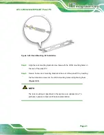
Figure 3-30: Arm Mounting
3.12.5 Stand Mounting
To mount the AFL3-W10A/12A/W15A-BT using the stand mounting kit, please follow the
steps below.
Step 1:
Locate the screw holes on the rear of the AFL3-W10A/12A/W15A-BT. This is
where the bracket will be attached.
Step 2:
Align the bracket with the screw holes.
Step 3:
To secure the bracket to the AFL3-W10A/12A/W15A-BT insert the retention
screws into the screw holes and tighten them.
Summary of Contents for AFL3-12A-BT
Page 15: ...AFL3 W10A 12A W15A BT Panel PC Page 1 1 Introduction Chapter 1...
Page 28: ...AFL3 W10A 12A W15A BT Panel PC Page 14 2 Unpacking Chapter 2...
Page 33: ...AFL3 W10A 12A W15A BT Panel PC Page 19 3 Installation Chapter 3...
Page 69: ...AFL3 W10A 12A W15A BT Panel PC Page 55 4 BIOS Setup Chapter 4...
Page 101: ...AFL3 W10A 12A W15A BT Panel PC Page 87 5 System Maintenance Chapter 5...
Page 106: ...AFL3 W10A 12A W15A BT Panel PC Page 92 6 Interface Connectors Chapter 6...
Page 121: ...AFL3 W10A 12A W15A BT Panel PC Page 107 Appendix A A Regulatory Compliance...
Page 126: ...AFL3 W10A 12A W15A BT Panel PC Page 112 B Safety Precautions Appendix B...
Page 132: ...AFL3 W10A 12A W15A BT Panel PC Page 118 C BIOS Menu Options Appendix C...
Page 135: ...AFL3 W10A 12A W15A BT Panel PC Page 121 Appendix D D Watchdog Timer...
Page 138: ...AFL3 W10A 12A W15A BT Panel PC Page 124 Appendix E E Error Beep Code...
Page 140: ...AFL3 W10A 12A W15A BT Panel PC Page 126 Appendix F F Hazardous Materials Disclosure...


