AFL2-17A/AB-H61
P a g e 72
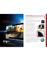
Figure 5-25: DB-9 Serial Port Connector
S te p 3:
Secure the connector
. Secure the serial device connector to the external
interface by tightening the two retention screws on either side of the connector.
S tep 0:
The pinouts of the RS-232 serial ports are shown below.
Pin
Description
Pin
Description
1
NDCD1
2
NSIN1
3
NSOUT1
4
NDTR1
5
GND
6
NDSR1
7
NRTS1
8
NCTS1
9
XRI1
10
NDCD2
11
NSIN2
12
NSOUT2
13
NDTR2
14
GND
15
NDSR2
16
NRTS2
17
NCTS2
18
XRI2
Table 5-4: RS-232 Serial Ports Pinouts (COM1, COM2)
Summary of Contents for AFL2-17A-H61-i3/PC-R12
Page 17: ...AFL2 17A AB H61 Page XVII Figure C 40 Symantec Ghost Window 242 ...
Page 21: ...AFL2 17A AB H61 Page 1 1 Introduction Chapter 1 ...
Page 34: ...AFL2 17A AB H61 Page 14 2 LED Light Bar Optional Chapter 2 ...
Page 57: ...AFL2 17A AB H61 Page 37 3 Detailed Specifications Chapter 3 ...
Page 63: ...AFL2 17A AB H61 Page 43 4 Unpacking Chapter 4 ...
Page 68: ...AFL2 17A AB H61 Page 48 5 Ins tallation Chapter 5 ...
Page 97: ...AFL2 17A AB H61 Page 77 Chapter 6 6 Sys tem Motherboard ...
Page 133: ...AFL2 17A AB H61 Page 113 Figure 6 36 LCD panel Selection Jumper Location ...
Page 134: ...AFL2 17A AB H61 Page 114 7 Sys tem Maintenance Chapter 7 ...
Page 143: ...AFL2 17A AB H61 Page 123 8 BIOS Setup Chapter 8 ...
Page 180: ...AFL2 17A AB H61 Page 160 9 Software Drivers Chapter 9 ...
Page 216: ...AFL2 17A AB H61 Panel PC Page 196 10 Cooling Management Cons ole iCMC Chapter 7 ...
Page 225: ...AFL2 17A AB H61 Panel PC Page 205 A Safety Precautions Appendix A ...
Page 230: ...AFL2 17A AB H61 Panel PC Page 210 B BIOS Menu Options Appendix B ...
Page 233: ...AFL2 17A AB H61 Panel PC Page 213 Appendix C C One Key Recovery ...
Page 241: ...AFL2 17A AB H61 Panel PC Page 221 Figure C 5 Partition Creation Commands ...
Page 274: ...AFL2 17A AB H61 Panel PC Page 254 D Hazardous Materials Dis clos ure Appendix D ...