background image

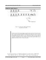
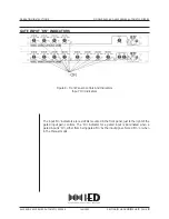
ON/OFF SWITCH AND POWER LED

The power On/Off switch is of the push-push type. When it is ‘Off’ it protrudes from the

front panel. When it is ‘On’, it is almost flush with the front panel. Press the button, then

release it to switch from ‘On’ to ‘Off’ or from ‘Off’ to ‘On’.

The green LED ‘Power On’ indicator is located to the left of the On/Off switch. It is illumi-

nated when power is ‘On’. If the switch is in the ‘On’ position and the LED indicator is not

illuminated, check the power cord, the fuse, and the AC outlet.

SECTION

4

GROUP

20

SUB

C

PAGE

2

JAN 1993

4400 AND 4800 SERIES AUTOMATIC MIXERS

MODELS 4400 AND 4800 SERIES AUTOMATIC MIXERS

OPERATING INSTRUCTIONS

Innovative Electronic Designs, Inc. 9701 Taylorsville Road Louisville, Kentucky 40299 USA

Phone: (502) 267-7436 Fax: (502) 267-9070 Internet: http://www.iedaudio.com

h

h

h

h

h

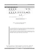
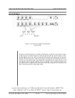
Figure 1 - Front Panel Controls and Indicators

Power switch and indicator LED

Summary of Contents for 4400 Series

Page 1: ...on of the system and setup of the options is described in the installation instructions Section 4 Group 20 Sub B This document describes the operation of the operator controls and indicators for the 4...

Page 2: ...llumi nated when power is On If the switch is in the On position and the LED indicator is not illuminated check the power cord the fuse and the AC outlet SECTION 4 GROUP 20 SUB C PAGE 2 JAN 1993 4400...

Page 3: ...emoved When the switch is in the Manual position there is no gating function The gated inputs are forced On and remain On at all times as do the red LED input On indicators See page 9 for additional i...

Page 4: ...available to the mi crophones provided that the setup jumpers are in the proper position Refer to the in stallation instructions Section 4 Group 20 Sub B SECTION 4 GROUP 20 SUB C PAGE 4 JAN 1993 4400...

Page 5: ...ween12 o clock and 3 o clock position Adjust each input individually to the desired level Finally adjust the overall level with the Output controls The table below describes typical attenuation versus...

Page 6: ...A Auxiliary Input remote control is installed the front panel Auxiliary In put gain controls are not functional SECTION 4 GROUP 20 SUB C PAGE 6 JAN 1993 4400 AND 4800 SERIES AUTOMATIC MIXERS MODELS 4...

Page 7: ...gating sensitivity of the gated inputs is independent of the front panel level control setting The table below describes typical attenuation versus pot rotation 4400 AND 4800 SERIES AUTOMATIC MIXERS J...

Page 8: ...s are made with the small screwdriver which is supplied with the mixer The position of the pot may be determined by observing the orientation of the slots in the shaft When shipped from the factory th...

Page 9: ...r for a gated input is illuminated when a gated input is On either from being gated On by the input signal forced On or when in the Manual mode 4400 AND 4800 SERIES AUTOMATIC MIXERS JAN 1993 SECTION 4...

Page 10: ...993 4400 AND 4800 SERIES AUTOMATIC MIXERS MODELS 4400 AND 4800 SERIES AUTOMATIC MIXERS OPERATING INSTRUCTIONS Innovative Electronic Designs Inc 9701 Taylorsville Road Louisville Kentucky 40299 USA Pho...

Reviews: