background image


3


1.  Important  Safety  Instructions 


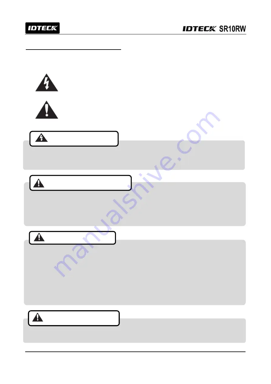
The  description  below  is  to  keep  user’s  safety  and  prevent  any  product  damage.  Please  full
y  read  these  instructions  and  use  the  product  properly.   


Danger:  This  symbol  indicates  that  incorrect  handling  of  the  product  may  resu

lt  in  serious  injury  or  death.


Warning:  This  symbol  indicates  that  incorrect  handling  of  the  product  may  res
ult  in  injury  or  property  damage. 


- Only use the standard voltage (DC +12V / 350mA).   

- If the product emits smoke or smells, stop using the product. Unplug the product from DC power source 

and contact nearest service center.


-  Do  not  install  the  product  in  a  place  subject  to  humidity,  dust  (metallic


dust)  or  splashing  water 

(raindrops).     

- Do not install the product in a place not meeting the operating humidity and temperature specified in the 

specification. 

- Do not install the product with tools such as driver in hand when power is being supplied. 


- Do not drop liquid onto the product such as water and give the product a severe shock.   

- Do not place magnetic objects near the product.   
- Do not replace the wiring cables installed by experts. 
- Do not use the product under direct sunlight or in a heat-producing place such as a place near a heating 

apparatuses.   

- If you want to relocate the installed product, turn power off and then move and reinstall it. 
- Do not use flammable sprays or objects near the product.   
- Do not let anyone but the manger touch the product except using it for normal purpose

.


- If liquid has been spilled on the product, unplug it first. 


- Do not clean the product with water. Clean gently with dry cloth or towel. 

- Do not use chemicals such as benzene, thinner or acetone for cleaning.


CAUTIONS ABOUT INSTALLATION 


CAUTIONS ABOUT POWER 


CAUTIONS ABOUT USAGE 


CAUTIONS ABOUT CLEANING 


Summary of Contents for SR10RW

Page 1: ...User s Manual 13 56MHz MIFARE Contactless Smart Card Reader Writer ...

Page 2: ...ntifying Supplied Parts 5 6 Installation 6 7 Color Coded Wiring Table 8 8 Output Format 9 9 Wire Connection to Access Controller 11 10 Operation 12 11 Troubleshooting 14 12 FCC Registration Information 15 13 Warranty Policy and Limitation of Liability 16 14 How to Make RMA Request After Sales Service 17 ...

Page 3: ...perature specified in the specification Do not install the product with tools such as driver in hand when power is being supplied Do not drop liquid onto the product such as water and give the product a severe shock Do not place magnetic objects near the product Do not replace the wiring cables installed by experts Do not use the product under direct sunlight or in a heat producing place such as a...

Page 4: ...y controller using methods of RS232 and RS485 Three LED indicators of red and green inside Piezo buzzer sound will guarantee you accurate and reliable system operations 3 Features 13 56MHz MIFARE Contactless smart Card Reader Writer Read Range Up to 4 inch 10cm Read the Card which is issued by PRG2000RW Smart Card Read Write Programmer RS232 RS485 default 26 34bit Wiegand selectable Output Format ...

Page 5: ...le LED Indicator 3 Array LED Indicators Red Green Beeper Piezo Buzzer Operating Temperature 35 to 65 C 31 F to 149 F Operating Humidity 10 to 90 relative humidity non condensing Color Dark Pearl Gray Material Polycarbonate Dimension W x H x T 1 8 X 4 5 X 0 88 47mm X 115mm X 22mm Weight 120g 0 26lb Certification FCC CE KCC RoHS 5 Identifying Supplied Parts Please unpack and check the contents of th...

Page 6: ...talled on the wall then skip this step 6 2 Fixing a Tamper Magnet to the wall Attach a tamper magnet with tools such as double sided tape on the left of the bottom hole that you drilled in 6 1 Refer to the figure below 6 3 Fixing Reader Module Put reader cable into the center hole and fix the reader module using two 6 32 or M3 screws 6 4 Putting on the Cover Put on cover into the reader module and...

Page 7: ...d The typical read distance specification 2 4 inches at 12VDC refers to operation without metal in the vicinity of the Reader The read distance will be reduced if metal is installed nearby The SR10RW generate a magnetic field on all sides of the Reader Any metal that conducts electricity especially metal that contains iron steel or copper will interfere with the field and reduce the effective spac...

Page 8: ...r 12V Red Power Ground GND Black ABA Track II CP Out Orange Wiegand Data 0 Out ABA Track II Data Out Green Wiegand Data 1 Out ABA Track II Clock Out White Buzzer Control In Blue LED Control In Yellow Tamper Switch Out Gray RS232 TX Purple RS232 RX Brown RS485 A Pink RS485 B Cyan Cut out the tail connector before installation Two readers can simultaneously read the same badge or tag if the distance...

Page 9: ... 25 4byte ID number 0000000001 4 294 967 295 Bit 10 25 ID number 00000 65 535 Bit 26 Odd parity of bit 14 bit 25 Bit 34 Odd parity of bit 18 bit 33 2 Timing diagram 8 2 ABA Track II Magstripe output format 1 Data format for Card numbers 3 5V 0 5V 100uS 1mS Data 0 100uS 100uS Data 1 3 5V 0 5V 5V 5V 0V 0V Start Character 11010 Hex B ID number 1248P 0000000001 4294967295 low bit first odd parity last...

Page 10: ...V 3V Space 0 Mark 1 8 Data Bits 2 Stop Bits Indeterminate Region Data packet corresponding to ASCII character A Start Bit 0 1 0 0 0 0 0 1 0 LSB MSB 0V Start Character 11010 Hex B PIN 1char to 8char low bit first odd parity last LRC Zero bit Zero bit 10bit CLK RD1 Data RD0 1240us 940us 6000us 6000us CP 1544us ...

Page 11: ...11 9 Wire Connection to Access Controller ...

Page 12: ...is working the green LED stays on This function is used for changing the LED color representing standby from red to green and applied to make various modifications according to the different I O setting of the controller For more information about the I O setting of the controller refer to the controller s user manual 10 4 Buzzer Control You can control the buzzer of the device at your preference ...

Page 13: ...an 8 channel DIP switch and the switch is used to set Board ID RS232 RS485 Temper output and Initialization Switch Number Description No 1 5 Board ID Setting See the Board ID Example below No 6 RS232 or RS485 0 RS232 1 RS485 No 7 Tamper output enable disable 0 Enable 1 Disable No 8 Initialization For initialization switch on to 1 position and keep it about 1 5 seconds and then switch down to 0 pos...

Page 14: ...e is Serial Number and another is to encode desired data in sector and block Being the other confirm to same format of issued card and reader Contact card publisher or buying company to confirmation usage 4 Don t reading despite confirmation from step 1 to step 3 contact RMA center When sounding buzzer and being on LED faintly at impressed voltage Cause At installing reader whether use adapter les...

Page 15: ...tion is subject to the following two conditions 1 This device may not cause harmful interference and 2 This device must accept any interference received including interference that may cause undesired operation This equipment has been tested and found to comply with the limits for a Class B Digital Device pursuant to Part 15 of the FCC Rules These limits are designed to this equipment generates us...

Page 16: ...ECK does not and cannot know who is present what property is located where this product will be used it would be extremely difficult to determine the actual damages that may result from a failure of the product to perform as anticipated and the low price of this product is based upon the nature of the product provided and the limited liability that IDTECK assumes IDTECK IS NOT RESPONSIBLE FOR ANY ...

Page 17: ...oduct without RMA Code is not accepted If you have any questions or problems regarding the RMA services please contact us using the following contact information below Friendly representatives at IDTECK are always standing by to provide the best after sales services IDTECK Headquarter 5F Ace Techno Tower B D 684 1 Deungchon Dong Gangseo Gu Seoul 157 030 Korea Tel 82 2 2659 0055 Fax 82 2 2659 0086 ...

Page 18: ...td The specifications contained in this manual are subject to change without notice at any time 5F Ace Techno Tower B D 684 1 Deungchon Dong Gangseo Gu Seoul 157 030 Korea Tel 82 2 2659 0055 Fax 82 2 2659 0086 E mail webmaster idteck com ...

Reviews: