16
REVISION A 09/15/14
82P33714/33814 EVALUATION BOARD
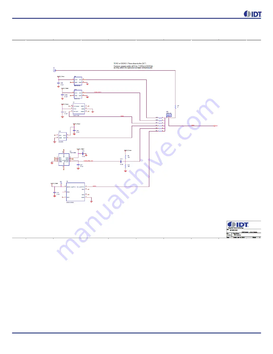
Figure 19. 82P33x14 Evaluation Board Schematics - Page 2: Reference Selection
Page 1: ...hich OUT1 2 7 8 9 10 are single ended outputs OUT3 4 5 6 are differential outputs MFR_2K_1PPS and MFR_8K_1PPS are single ended outputs providing 2KHz and 8KHz frame sync signals respectively USB conne...
Page 2: ...clocks will be disqualified invalid Please note there are other criteria for an input clock to be invalid I2 C address bits I2C_AD 2 1 sets the lower 3 bit address of 7 bit I2C address with the least...
Page 3: ...r communicating with the PC running Timing Commander It is not used to provide any power source for the board When plugged in to the PC s USB port a green LED is lit Connecting the Board Other than in...
Page 4: ...nect the board as shown in Figure 2 2 Press HW Reset button on the board to reset the device This may not be necessary if the board is first powered up 3 Start Timing Commander software You will see o...
Page 5: ...left and 10 outputs are on the right side of the window For Input configuration most frequencies can be entered for IN01 IN6 and they will be automatically configured to be available to both DPLLs Fo...
Page 6: ...to IN02 10MHz click on the Input Buffer of IN02 the triangle symbol following frequency entry box a sub configuration window for IN02 is shown below In the window IN01 is selected as sync signal Figur...
Page 7: ...uration There are pull down items for each configuration parameter For example in Operation Mode section you can select Automatic or Free up to force Lock or Free run Different base frequencies can be...
Page 8: ...elect DPLL s bandwidth and damping factors during start acquisition and locked phases Always use Locked bandwidth damping This option will use the bandwidth and damping factor that are available when...
Page 9: ...However 19 2MHz and 10MHz based clocks are not supported by the default hardware profiles for the APLLs Therefore APLL1 APLL2 needs to be pre configured to the applicable VCO frequency To configure A...
Page 10: ...lect custom on DPLL1 as shown in Figure 10 Then click on Customize button and ignore the initial Timing Commander error Enter the values as shown in Figure 12 below Figure 12 Configure APLL2 Parameter...
Page 11: ...period Figure 14 Configure MRSYNC and MRFRSYNC 8 Connecting to the Board Configurations can be done before making the USB I2 C connection to the board Or connecting with the board can be established b...
Page 12: ...G 8263 to configure the DPLL for PEC S F which occurs when typically a IEEE 1588 algorithm is controlling the DCO with frequency offsets G 8273 2 to configure the DPLL for T BC Telecom Boundary Clock...
Page 13: ...The PLL operation status can be updated and viewed by clicking View Status button in GUI window The status window looks like the following Figure 17 Enabled input reference clock will show with a lit...
Page 14: ...14 REVISION A 09 15 14 82P33714 33814 EVALUATION BOARD Figure 17 DPLL Status Window...
Page 15: ...REVISION A 09 15 14 15 82P33714 33814EVALUATIONBOARD Board Schematics Figure 18 82P33x14 Evaluation Board Schematics Page 1 Block Diagram...
Page 16: ...16 REVISION A 09 15 14 82P33714 33814 EVALUATION BOARD Figure 19 82P33x14 Evaluation Board Schematics Page 2 Reference Selection...
Page 17: ...REVISION A 09 15 14 17 82P33714 33814EVALUATIONBOARD Figure 20 82P33x14 Evaluation Board Schematics Page 3 I O Termination...
Page 18: ...18 REVISION A 09 15 14 82P33714 33814 EVALUATION BOARD Figure 21 82P33x14 Evaluation Board Schematics Page 4 I2C EEPROM...
Page 19: ...REVISION A 09 15 14 19 82P33714 33814EVALUATIONBOARD Figure 22 82P33x14 Evaluation Board Schematics Page 5 Power Supply 1...
Page 20: ...20 REVISION A 09 15 14 82P33714 33814 EVALUATION BOARD Figure 23 82P33x14 Evaluation Board Schematics Page 6 Power Supply 2...
Page 21: ...sented only as a guide and does not convey any license under intellectual property rights of IDT or any third parties IDT s products are not intended for use in applications involving extreme environm...
Page 22: ...Mouser Electronics Authorized Distributor Click to View Pricing Inventory Delivery Lifecycle Information IDT Integrated Device Technology 82EBP33814...