


Part 1 – Introduction
15
Rear Panel Connections
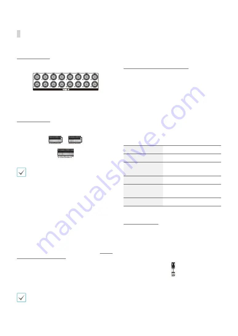
Video Connection
Video Input
1
2
4 5
6
3
7
8
9
0
Connect the coaxial cables from the video sources to the
composite Video In connectors or BNC connectors.
Alarm Connection
Connect alarm connectors to these ports.
1
2
4 5
6
3
7
8
9
0
1
2
4 5
6
3
7
8
9
0
Press down on the button and insert the cable into
the opening. Release the button and then pull on the
cable slightly to ensure it is held securely in place. To
disconnect the cable, press down on the button again
and pull the cable out.
●
Alarm In 1 through 16
This DVR is capable of responding to event signals
from external alarm in devices. Connect mechanical
or electrical switches to AI 1 through 16 and the GND
(ground) connector. In order to be recognized by the
DVR, the signal from an alarm in device must be less
than 0.3V (Normally Open) and maintained for at least
0.5 seconds. The alarm in voltage range is 0V to 5V. For
more information on alarm in setup, refer to the
Alarm-
In in the operation manual
.
●
GND (Ground)
Connect alarm in or out's ground cable to the GND
connector.
All connectors marked "GND" are common connectors.
●
NC/NO (Relay Alarm Outputs)
This DVR is capable of activating/deactivating buzzers,
lights, and other external devices. Connect the device
to the C and NO (Normally Open) connectors. NC/NO is
a relay output which sinks 2A@125VAC and 1A@30VDC.
For more information on alarm out setup, refer to the
Alarm-Out in the operation manual
.
●
ARI (Alarm Reset In)
An external signal to the Alarm Reset In can be used to
reset both the Alarm Out signal and the DVR’s internal
buzzer. Mechanical or electrical switches can be wired to
the ARI (Alarm Reset In) and GND (Ground) connectors.
The threshold voltage is below 0.3V and should be
stable at least 0.5 seconds to be detected. Connect the
wires to the ARI and GND connectors.
●
Connector Arrangement
AI1 through AI16
Alarm In 1 through 16
GND
Ground
NC
Relay Alarm Out (Normally
Closed)
C
Relay Common
NO
Normally Open Relay Alarm
Out
ARI
Alarm Reset In
RS-485 Connection
This DVR supports the RS-485 half-duplex serial
communication protocol for connecting to external
devices such as POS units. The RS-485 connector can
also be used to control PTZ (pan, tilt, zoom) cameras.
Connect RX+/TX+ and RX–/TX– of the control system to
the + and – (respectively) of the DVR.
1
2
4 5
6
3
7
8
9
0


